
User Manual


8/17/2005 CavitronRF Combo - DFU Draft 08-01-05 Rev8doc
DRAFT
Page 9 of 18
Power – (Display) Lights when the Power ON/OFF Control Switch is ON.
Low Battery – (Display) Lights when the footswitch battery power is approaching end of life. Replace
batteries as instructed in Section 5.8.
Service – (Display) Lights when the system is not functioning properly. This display has two distinct
modes. A blinking light indicates an incorrect set-up in the system, such as a missing handpiece. Correct
the set-up and press the footswitch for a second to stop the blinking. The service light may blink briefly
while installing or removing your insert. Should this occur, release and press the footswitch for a second
and the light will stop blinking. A steady light indicates an internal operating parameter shift. The system
will still function properly without harm to user or patient. Have your system serviced. Refer to Section
10.2 for Technical Support and Repairs.
Boost – (Display) Lights when the Boost Mode has been activated by the footswitch (fully depressed to 2
nd
position).
Blue Zone– (Display) Lights when the Ultrasonic Power Control knob is positioned in the blue zone of the
power scale. (Use the Blue Zone extended low-power range for effective subgingival debridement and
greater patient comfort during definitive therapy.)
Rinse – (Display) Lights when the Ultrasonic Power Control knob is turned fully counter clockwise. With
an insert in the handpiece, activate the footswitch and lavage, with minimal cavitation will occur. (Use the
Rinse mode when irrigation is wanted to flush the procedural area.)
Purge – (Display and Control) Lights when the Purge function is activated. To activate Purge, remove
insert from the handpiece, press the Purge button and water will purge through system lines for 2 minutes.
To deactivate mode during the 2 minute cycle, press Purge button again or press Foot Control.
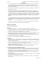
6.3 Handpiece / Cable Connection
(Picture)
• The Cavitron® JET-Mate Sterilizable Handpiece accepts all Cavitron® 30K Ultrasonic Inserts and
JET air polishing insert.
• Lavage Control – Turn the Lavage Control to select flow rate during system operation. Clockwise
increases flow at insert tip, counter clockwise decreases flow. The flow rate through the handpiece
also determines the temperature of the lavage. Lower flow rates produce warmer lavage. Higher flow
rates produce cooler lavage. If the handpiece becomes warm, increase the flow rate. With experience
you will be able to determine the best flow rate setting for optimum operating efficiency and patient
comfort.
• Prior to connecting, align the handpiece and Cable Assembly electrical connections. If Cable
Assembly does not seat into handpiece, gently rotate handpiece until contacts align.
• Powder Delivery Port – creates an airtight seal between the air polishing insert and the handpiece.
• Swivel Feature – reduces cable drag as handpiece rotates during procedures.
• Insert Port – creates a watertight seal between the insert and the handpiece.
• Soft Grip – provides an ergonomic and comfortable grasp of the handpiece.
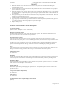
6.4 Cavitron® 30K™ Ultrasonic Inserts
(Picture from current DFU’s)
O-Ring
Provides a watertight seal when the insert is fully seated in the handpiece. O-ring should be replaced when
worn.
Connecting Body
Transfers and amplifies mechanical motion of stack to insert tip.
Magnetostrictive Stack
Converts energy provided by the handpiece into mechanical oscillations used to activate the insert tip.
Warms lavage for patient comfort.