
User Manual


10
of the connector in an appropriate container and allow
water to drain. To remove the hose from the system,
push on the outer ring of the system’s water inlet and
gently pull out the water line.
• Turn Tap-On
TM
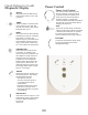
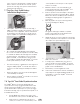
Wireless Foot Pedal over and using a
Philips screwdriver carefully remove battery cover screw
and battery cover. If applicable, remove used batteries
and install two new “AA” batteries as shown. Do not
depress Tap-On
TM
Foot Pedal while installing batteries.
• The communication light will blink for approximately
two seconds to indicate the Tap-On
TM
Foot Pedal’s ability
to communicate with the unit. If the light does not blink,
check the batteries. If the batteries are good and the
light doesn’t blink, a communications error may exist.
To re-establish communication with Tap-On
TM
Foot Pedal
review Synchronization procedure, section 7.10.
• The remote frequency communication can be bypassed
using the auxillary Tap-On
TM
Foot Pedal cable. Refer to
Section 11.2 Technical Support and Repair for further
action.
• Replace the battery cover and screw and hand tighten
cover with Philips screwdriver.
• Remove batteries if Tap-On
TM
Foot Pedal is to be stored
for an extended period of time.
7.8 Tap-On
TM
Foot Pedal Synchronization
The Tap-On
TM
Wireless Foot Pedal supplied with your
system has been factory synchronized with the base unit.
Should a replacement Tap-On
TM
Foot Pedal be necessary,
synchronization will be required prior to system operation.
Perform the following steps to synchronize the Tap-On
TM
Foot
Pedal with the base unit.
1. Turn the MainPower switch located at the center
front underside of the system to the OFF (O) position.
2. Install a new set of “AA” batteries into the foot
control (see section 7.9). Leave the battery cover
of the Tap-On
TM
Foot Pedal open so the red push
button is accessible.
3. Maintain a distance of no more than 10 feet (3
meters) between the base unit and Tap-On
TM
Foot
Pedal during the synchronization process.
4. Remove any inserts from the handpiece and adjust
the Power Level Control out of Rinse Mode. Turn the
Main Power switch to the ON (I) position and wait for
the Diagnostic Display graphics to light (refer to
Section 8.2).
5. While all graphics are lit, press the Purge button,
located on the Diagnostic Display.
The graphics will begin to blink in a sequential
pattern, representing the synchronization mode.
This mode will last 5 to 6 seconds.
6. During this mode, press the red button located in the
battery compartment of the Tap-On
TM
Foot Pedal. This
will complete the synchronization process.
7. Synchronization is successful when all graphic lights
blink at the same time.
8. To verify proper communication, press the foot
control to the Boost position (Tap-On
TM
Foot Pedal
fully depressed – 2
nd
position) and ensure the Boost
graphic on base unit illuminates.
9. Attach battery cover and tighten the screw.
10. In the event communication cannot be established,
temporarily use the supplied Auxillary Tap-On
TM
Foot
Pedal Cable to connect the Tap-On
TM
Foot Pedal
directly to the unit.
Look for blinking
communications
light.
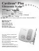
7.7 Tap-On
TM
Foot Pedal Battery
Installation/Replacement
PURGE