Vulcan® Furnace Service Manual Models: A-130 A550 A-1750 3-130 3-550 3-1750 3-550PD 3-550A 3-1750A CERAMCO ®
SAFETY SAFETY FIRST • Don’t bypass the power cord’s ground lead with two-wire extension cords or plug adaptors. • Don’t disconnect green/yellow safety-earth ground wire that connects the ground lug of the power receptacle to the chassis ground. • Don’t plug in the power cord until directed by the installation instructions. • Don’t repair the furnace unless you are a qualified technician and know how to work with hazardous voltages.
TABLE OF CONTENTS SECTION 1 CIRCUIT DESCRIPTION 1.1 1.2 1.2.1 1.2.2 1.2.3 1.2.4 A-CONTROL INTRODUCTION ..........................................1-1 CIRCUIT DESCRIPTION ..............................1-1 Analog Meter Readout ...............................1-1 Front Panel Controls ..................................1-1 Muffle Control ...........................................1-1 Power Supply ............................................1-1 SECTION 2 TROUBLESHOOTING 2.1 2.2 2.3 2.3.1 2.3.2 2.3.3 2.4 2.5 2.
SECTION 1 - CIRCUIT DESCRIPTION - A-CONTROL 1.1 INTRODUCTION The purpose of this section is to familiarize the user or service personnel with the circuit level operation of the VULCAN. This knowledge is necessary to aid in troubleshooting of a unit's failure and may also allow the user to gain greater insight into the VULCAN’s versatility for particular applications.
SECTION 2 - TROUBLESHOOTING - A-CONTROL 2.3.3 TRIAC DRIVE 2.1 FACTORY REPAIR A current pulse from U2 pin 6 of about 60mA will turn on the gate of the muffle triac which in turn will then carry the full load current. The voltage across the triac is now at 1-2 Vac. In order to comply with norms limiting the frequency at which a kW size load may be connected to the main line (fluorescent tubes "flickering") a proportional temperature control is provided by means of burst firing the triac.
SECTION 2 - TROUBLESHOOTING - A-CONTROL Leaking capacitors will often have a decreased voltage across their terminals.
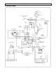
SECTION 2 - TROUBLESHOOTING - A-CONTROL 2.5 BLOCK DIAGRAM 120/240V 60/50Hz Line Power Supply D1,C1,R11 Return Cabinet +6.8V -8.
SECTION 2 - TROUBLESHOOTING - A-CONTROL 2.
SECTION 2 - TROUBLESHOOTING - A-CONTROL 2.
SECTION 2 - TROUBLESHOOTING - A-CONTROL 2.
SECTION 3 - ADJUSTMENT/CALIBRATION - A-CONTROL 3.1 SCOPE 3.4 CIRCUIT BOARD CALIBRATION This section gives the procedures to be used for the calibration and specification verification of the VULCAN. The furnace specifications are given in the Owner & Operator’s Manual. Calibration of the VULCAN circuit board is performed in one single step. 3.4.1 REQUIRED TEST EQUIPMENT - Multimeter - Pot adjustment tool 3.2 FACTORY REPAIR WARNING With control drawer opened, dangerous voltage points may be exposed.
SECTION 4 - CIRCUIT DESCRIPTION - 3-STAGE 4.2.4 POWER SUPPLY 4.1 INTRODUCTION The purpose of this section is to familiarize the user or service personnel with the circuit level operation of the VULCAN. This knowledge is necessary to aid in troubleshooting of a unit's failure and may also allow the user to gain greater insight into the VULCAN’s versatility for particular applications.
SECTION 5 - TROUBLESHOOTING - 3-STAGE 5.1 FACTORY REPAIR 5.3 TROUBLESHOOTING GUIDES DENTSPLY Ceramco maintains a factory repair department for those customers not possessing the necessary personnel or test equipment to maintain the VULCAN. If a unit is returned to the factory for calibration or repair, a detailed description of the specific problem should be attached to minimize turnaround time. Call factory for PR number before shipping at 1-800-835-6639. 5.3.1 POWER SUPPLY 5.
SECTION 5 - TROUBLESHOOTING - 3-STAGE 5.3.7 FAN DRIVE (OPTIONAL ACCESSORY) 5.4.3 TRIAC The 12V DC fan is controlled by a FET device which is activated by the microprcessor. At its highest setting (9), the fan receives the full 12V DC. At lower settings the fan receives +12V pulses, to reduce the rpm's. The gate to power line return voltage (K1) under load measures typically 1-2 Vac, while the MT2 to return voltage measures between 1.3-1.8 Vac.
SECTION 5 - TROUBLESHOOTING - 3-STAGE 5.5 ERROR CODES ERR 1 MUFFLE OVER TEMPERATURE The controller monitored a temperature above °C. This could mean a faulty thermocouple (mV reading too high) or an erratic thermocouple performance (the temperature readout is not stable at elevated temperatures). ERR 2 OPEN TC DETECTED To check for open TC, turn power to furnace off and short TC input terminals. Turn power back on. If ERR 2 disappears, then replace TC. Possible solutions: Change PCB if problem persists.
SECTION 5 - TROUBLESHOOTING - 3-STAGE 5.
SECTION 5 - TROUBLESHOOTING - 3-STAGE 5.6 DIAGNOSTIC TABLES POWER SUPPLY Fault Setup Check Results desired No DC output and no DC to U11-2 (15-30V) PT1 to PT4 Power off Fuse < 1 ohm Not shorted or open Not shorted or open MICROPROCESSOR Fault Setup Check Results desired Nonfunctional operation N/A U9-3, 2 X1 U9-26 U9-9 U9-10 4.9MHz, sinusoid approximately 0-4V >4.
SECTION 5 - TROUBLESHOOTING - 3-STAGE 5.
SECTION 5 - TROUBLESHOOTING - 3-STAGE 5.6 DIAGNOSTIC TABLES ANALOG CIRCUITRY Fault Setup Check Results desired Muffle heats but display shows same temperature N/A YELL2 U4 D1 TC yellow connected Gain approx. 20 1.23V Erratic temperature display N/A D1 U4-11 & 12 1.23V stable DC stable Temperature drift Hi T = 960°C RED 39-40mV stable U4-13 mV stable (.
SECTION 5 - TROUBLESHOOTING - 3-STAGE 5.7 BLOCK DIAGRAM Switching Power Supply +12V 90-264V 60/50Hz Pg 5-9 U1, U2 Thermocouple Zero Crossing AMP U1 U9 U4 Multiplexed A/D U8 Microprocessor M Pg 5-11 D1 + RT1 Cold Jct.
SECTION 5 - TROUBLESHOOTING - 3-STAGE 5.
SECTION 5 - TROUBLESHOOTING - 3-STAGE 5.
SECTION 5 - TROUBLESHOOTING - 3-STAGE 5.
SECTION 5 - TROUBLESHOOTING - 3-STAGE 5.
SECTION 5 - TROUBLESHOOTING - 3-STAGE, PD, A 5.
SECTION 6 - ADJUSTMENT/CALIBRATION - 3-STAGE 6.3.2 DOOR, LIFT DRAG ADJUSTMENT 6.1 SCOPE This section gives the procedures to be used for the calibration and specification verification of the VULCAN. The furnace specifications are given in the Owner & Operator’s Manual. The lift drag force is controlled by a set of friction washers on each of the upper pivot arms A wave spring should maintain a relatively constant force even after several thousand cycles.
SECTION 7 - SERVICE PARTS - A-CONTROL & 3-STAGE 7.1 ORDERING INSTRUCTIONS To order parts, select the part number required from the exploded view drawings on page 7.1. through page 7.6. The 130, 550, 1750 numbers refer to the particular size of furnace where the part number is different depending on the size. When ordering parts please have the following information available: 1. Serial number of furnace. 2. Date purchased. 3. Purchased where. 4. Symptom of failure. 5. Part number of replacement part. 6.
SECTION 7 - SERVICE PARTS - 3-550A & 3-550PD 7.
SECTION 7 - SERVICE PARTS - A-CONTROL, 3-STAGE, 3-550PD 7.4 CABINET PARTS NOTE: To convert to configurations shown, 9495115 - Retrofit Kit, is available for furnaces built prior to S/N 0626xxx.
SECTION 7 - SERVICE PARTS - A-CONTROL, 3-STAGE 7.4 CABINET PARTS FAN ASSY (9493986) 3-550A, 3-1750A FAN DUCT ASSY (9493970) 3-550A, 3-1750A 7.5 DOOR PARTS DOOR SPRING (9493368), 130 (9493908), 550 (9492754), 1750 (2 PL) SCREW 10-32 x .
SECTION 7 - SERVICE PARTS - A-CONTROL 7.6 A- CONTROLLER PARTS CONTROL PCB (R9493348) 100-120V A-130 (R9493449) 200-240V A-130 (R9493349) 100-120V A-550 (R9493450) 200-240V A-550 (R9493451) 200-240V A-1750 FUSE (20A) - S/N 9525 and 9320072 earlier SCREW, 6-32 x .
SECTION 7 - SERVICE PARTS - 3-STAGE, 3-550PD 7.7 3-STAGE CONTROLLER PARTS s CONTROL PCB, 3-550 PD,A (R9493446) 100-125V Replaced by R9495232 (Not Shown) (R9493447) 200-240V SCREW, 6-32 x .375 SCREW, 6-32 x 1.
SECTION 7 - SERVICE PARTS - 3-550PD 7.8 LIFT MECHANISM PARTS NUT, 1/4-20 HEX SCREW, 10-32 SEM BRACE (9493363) PIVOT ARM BRACKET, MOTOR LINKAGE (9493532) BOLT, SHOULDER .375 SCREW, #8-32 SEM BRACKET, MOTOR (9493362) SCREW #8 X.375 SCREW, #8 X .
SECTION 8 - DISASSEMBLY/REASSEMBLY - 3-STAGE 8.1 CONTROL DRAWER REMOVAL 8.2 TRIAC TOOLS: TOOLS: Phillips #2 screwdriver Phillips #2 screwdriver, 1/4" nut driver, needle nose pliers - To gain access to the electrical components and most other service jobs, removal of the control drawer is required. 8.2.1: Follow steps 8.1.1 through 8.1.2 of CONTROL DRAWER REMOVAL WARNING: Disconnect power cord from wall outlet before attempting to service the furnace. 8.2.
SECTION 8 - DISASSEMBLY/REASSEMBLY - 3-STAGE 8.3 MEMBRANE SWITCH TOOLS: Phillips screwdriver Knife of other sharp edged device 8.3.1: Follow steps 8.1.1 through 8.1.2 of CONTROL DRAWER REMOVAL Control PCB Membrane Switch Control Drawer 8.3.5: Place the new membrane switch by locating the bottom edge against the bottom of the recess. Membrane Switch 8.3.2: Control PCB Disconnect ribbon cable at control PCB DOT Membrane Switch 8.3.6: Connect ribbon connector 8.3.
SECTION 8 - DISASSEMBLY/REASSEMBLY - 3-STAGE 8.4 DISPLAY PCB TOOLS: Phillips screwdriver CAUTION! Use proper ESD grounding techniques when handling electronic components 8.4.1: Follow steps 8.1.1 through 8.1.2 of CONTROL DRAWER REMOVAL 8.4.5: Connect grey ribbon connector. Bend away from Display PCB so it won't cut into ribbon. 8.4.2: Disconnect grey ribbon connector. 8.4.3: Remove from snap-on standoffs. 8.4.4: Replace with new Display PCB.
SECTION 8 - DISASSEMBLY/REASSEMBLY - A-CONTROL 8.5 A-CONTROL PCB TOOLS: Phillips screwdriver Needle nose pliers 3/8" nut driver or wrench 1/4" nut driver 13 mm nut driver or pliers CAUTION! Use proper ESD grounding techniques when handling electronic component 8.5.5: Remove knob by pulling out and nut (13mm nut driver or pliers). 8.5.1: Follow steps 8.1.1 through 8.1.2 of CONTROL DRAWER REMOVAL. Remove muffle wires AC1 AC2 MT1 MT2 8.5.
SECTION 8 - DISASSEMBLY/REASSEMBLY - 3-STAGE 8.6A 3 STAGE CONTROL PCB - 9493980 TOOLS: Phillips screwdriver, Slotted screwdriver, Needle nose pliers CAUTION! Use proper ESD grounding techniques when handling electronic components 8.6.6: Remove thermocouple wires 8.6.1: Follow steps 8.1.1 through 8.1.2 of CONTROL DRAWER REMOVAL. DOT 8.6.2: Disconnect wires from power switch. 8.6.7: Remove 5 screws. 8.6.3: Disconnect ribbon connectors. 8.6.8: Squeeze plastic standoff and lift circuit board. 8.6.
SECTION 8 - DISASSEMBLY/REASSEMBLY 8.6B 3 STAGE CONTROL PCB – 9495232 CAUTION! Use proper ESD grounding techniques when handling components TOOLS: Phillips & Slotted Screwdrivers, Needle Nose Pliers Follow steps 8.1.1 through 8.1.
SECTION 8 - DISASSEMBLY/REASSEMBLY 8.7 DOOR ASSEMBLY/ ADJUSTMENT TOOLS: 5/32 Allen wrench Phillips head screwdriver If the door feels too stiff or too loose when lifting up and down, a tension adjustment can be made from the outside. 8.7.4: If door or door insulation needs replacement, remove the 4 screws on bottom of door (step 5.7.2) and slide from slide out assy. 8.7.1: If door tension is too loose tighten the screw on each side until the desired tension is reached. If too tight, loosen screw. 8.7.
SECTION 8 - DISASSEMBLY/REASSEMBLY 8.8 HEATING PLATES TOOLS: Phillips head screwdriver Small putty knife Note: Like the headlights on a car, if one heating plate burns out, the other will likely burn out soon. Therefore, it would be advisable to replace both plates at once. WARNING: Disconnect power from the wall outlet before attempting to service the furnace! Brake bond with putty knife rotate in 8.8.3: Pull out bad plate(s) (Rotate bottom of plate toward center of muffle).
SECTION 8 - DISASSEMBLY/REASSEMBLY 8.9 COMPLETE MUFFLE REPLACEMENT TOOLS: Phillips head screwdriver; small flat head screwdriver; needle nose pliers WARNING: Disconnect power from the wall outlet before attempting to service the furnace! 8.9.1: Follow steps 8.1.1 - 8.1.2 of CONTROL DRAWER REMOVAL. A-CONTROL 100, 120V HOOK UP 8.9.
SECTION 8 - DISASSEMBLY/REASSEMBLY 8.11 THERMOCOUPLE (3 STAGE CONTROL) TOOLS: bladed screwdriver phillips head screwdriver 1/4" nutdriver bracket WARNING: Disconnect power from the wall outlet before attempting to service the furnace! Wraparound Front Panel 8.9.11: Front panel must insert into offset bracket in wraparound 8.11.1: Follow steps 8.1.1 - 8.1.2 of control drawer removal 8.9.12: Check muffle resistance to verify wiring is correct before securing control drawer: 100V 120V A-130, 3-130 11.
SECTION 8 - DISASSEMBLY/REASSEMBLY 8.12 COMPLETE MUFFLE REPLACEMENT TOOLS: Phillips head screwdriver; bladed screw driver; needle nose pliers 8.12.1: Follow steps 8.1.1 - 8.1.2 of CONTROL DRAWER REMOVAL. REMOVE SCREWS 8.12.2: Close door and remove 6 screws on the front top of the furnace. Remove exhaust port 8.12.6: Pull/pry out muffle assy (with attached front panel) from wraparound REMOVE SCREWS REMOVE SCREWS 8.12.
SECTION 8 - DISASSEMBLY/REASSEMBLY 8.13 THERMOCOUPLE (3-550 PD) TOOLS: bladed screwdriver phillips head screwdriver 1/4" nutdriver bracket WARNING: Disconnect power from the wall outlet before attempting to service the furnace! Wraparound Front Panel 8.12.10: Front panel must insert into offset bracket in wraparound 8.13.1: Follow steps 8.1.1 - 8.1.2 of control drawer removal 8.12.
SECTION 8 - DISASSEMBLY/REASSEMBLY 8.14 POWER SWITCH Remove 2 screws TOOLS: Slotted screwdriver 8.14.1: Follow steps 8.1.1 through 8.1.2 of CONTROL DRAWER REMOVAL 8.14.2: Disconnect switch wires 8.13.3: Remove the 2 screws which support rear panel. 8.14.3: Remove switch by pressing in tabs. 8.13.4: Remove screw used to secure thermocouple and pull thermocouple from muffle. Pull thermocouple wire through brass grommet. 8.13.5: Replace with new thermocouple by reversing previous steps 8.11.1 thru 8.11.
SECTION 8 - DISASSEMBLY/REASSEMBLY 8.15 POWER DOOR MOTOR REPLACEMENT 8.15.5: Disconnect wires (Female quick connect terminals) from motor. Disconnect wires 8.15.1: Slide control drawer forward using steps 8.1.1 and 8.1.2 8.15.2: Slide muffle assembly forward using steps 8.1.3, 8.9.4, 8.9.5 and 8.9.6 (approximately 5 inches). 8.15.3: Remove the 2 screws which support rear panel. Remove 2 screws 8.15.6: Remove (4) screws to free motor Remove 2 screws Remove 2 screws 8.15.
PRODUCT SERVICE: Three methods of product service are available: • Telephone assistance available at the number listed below. • Return the unit for servicing using the instructions below. BEFORE RETURNING THE UNIT: • Call DENTSPLY for a PR (Product Return) number. This is used to track and identify your unit. Equipment received without this number may not be identifiable. • If you do not have the original packaging, please request replacement packaging to ensure the unit is not damaged in shipment.