BATTERY POWER LINE II Battery driven power tool system for orthopedics and traumatology Instruments and Implants approved by the AO Foundation. This publication is not intended for distribution in the USA.
TABLE OF CONTENTS INTRODUCTION OPERATING INSTRUCTIONS CARE AND MAINTENANCE General Information 3 Drive Units 8 Universal Battery Charger II 13 Battery Pack (battery casing with inserted battery) 14 Battery Reamer/Drill II 22 Attachments for Battery Reamer/Drill II 23 Battery Oscillator II 39 Battery Reciprocator II 42 General Information 45 Preparation prior to Cleaning 47 Manual Cleaning Instructions 48 Automated Cleaning Instructions with Manual Pre-cleaning 51 Lu
Table of contents TROUBLESHOOTING 69 SYSTEM SPECIFICATIONS 75 ELECTROMAGNETIC COMPATIBILITY Accompanying Documents ORDERING INFORMATION 84 Warning This description alone does not provide sufficient background for the direct use of the product. Instruction by a surgeon experienced in handling this product is highly recommended.
Introduction GENERAL INFORMATION Intended use The Battery Power Line II is designed for the use in orthopedic and traumatology surgery of skeleton, i.e. • Drilling • Reaming • Inserting/removing K-Wires/Pins • Cutting bone.
Introduction General Information Indications Drilling, reaming, inserting/removing K-Wires/Pins, sawing on the bone of human skeleton. For detailed indications, refer to corresponding “Techniques Guides” of the implant system used.
Note: To ensure proper operation of the tool, annual maintenance by a SynthesService Center is neces sary. The manufacturer shall assume no responsi bility for damage resulting from improper opera tion, neglected or unauthorized maintenance of the tool. Notes: • Always wear personal protective equipment (PPE) including safety goggles when handling with the BPL II system. • To avoid injuries, the locking mechanism of the tool has to be activated before every manipulation and when laying the tool down, i.
Introduction General Information Accessories/scope of delivery The Battery Power Line II consists of three different handpieces, a battery casing, a battery and a range of attachments designed for the system. Storage and transport Only use the original packaging for dispatch and transport as otherwise damage may occur. If this is not possible, please contact your local Synthes office. To charge the batteries only use the corresponding Synthes Universal Battery Charger II (05.001.204).
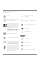
Explanation of symbols used The following symbols are applied to the device or individual components. Caution Consult the provided instructions for use before operating the device. S9 IP X4 The device is classified as type BF against electrical shock and leakage current. The device is suitable for use on patients according to the standards defined by IEC 60601-1: 2005 + CORR. 1 (2006) + CORR. 2 (2007) ANSI/AAMI ES60601-1:2005, Dated December 2005 and CAN/CSA-C22.2 No.
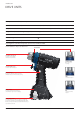
Introduction DRIVE UNITS Battery Reamer/Drill II (530.705) Speed (without attachment) 0–340 rpm (maximum speed varies with attachment) Torque (without attachment) 0–15 Nm (maximum torque varies with attachment) Weight of handpiece (including battery pack) 1565 g/3.4 lbs Cannulation B 4.0 mm Protection against electric shock BF Protection against water ingress IP X4 Cleaning brush (516.101) and Synthes Special Oil (519.970) included Technical data is subject to tolerances.
Battery Oscillator II (530.710) Speed 0–12 000 oscillations per minute Deflection 4.5° (0°/2.25°) Weight of handpiece (including battery pack) 1685 g/3.7 lbs Protection against electric shock BF Protection against water ingress IP X4 Synthes Special Oil (519.970) included Technical data is subject to tolerances.
Introduction Drive Units Battery Reciprocator II (530.715) Speed 0–14 000 oscillations per minute Stroke 4 mm Weight of handpiece (including battery pack) 1675 g/3.6 lbs Protection against electric shock BF Protection against water ingress IP X4 Synthes Special Oil (519.970) included Technical data is subject to tolerances.
Battery for Battery Power Line II Art. no. 530.630 Type Li-Ion (Lithium Ion) Voltage 14.8 V Capacity 1.5 Ah/22.2 Wh Charging Time typically < 60 minutes Technical data is subject to tolerances. Note: For further information on the correct method of charging, storing and using the battery, please refer to page 20ff.
Introduction Drive Units Compatibility between BPL and BPL II batteries Existing BPL handpieces are compatible with BPL II batteries The existing BPL handpieces (530.605, 530.610, 530.615) can be used with the new BPL II battery (530.630), battery casing (530.690) and sterile cover (530.660) as seen in Fig. 1. 530.605 530.690 Figure 1 Existing BPL batteries are compatible with BPL II handpieces The existing BPL battery (530.620), battery casing (530.680) and sterile cover (530.
Introduction UNIVERSAL BATTERY CHARGER II The Universal Battery Charger II (05.001.204) includes four independent charging bays. Each charging bay has three slots; the Battery Power Line II battery (530.630) fits into the top slot. Front view 1 2 3 Note: In order that the BPL II battery can be recog nized and charged by the UBC II, a minimum of firmware version 14.0* is required. If necessary, send the charger to a Synthes representative for a firmware update.
Operating Instructions BATTERY PACK (BATTERY CASING WITH INSERTED BATTERY) Synthes non-sterile batteries and advanced charging technology optimize intraoperative battery capacity, maximize battery lifespan and shorten turnaround time. One Universal Battery Charger II (05.001.204) for multiple Synthes battery-driven systems simplifies the charging process. Simple aseptic technique preserves the sterile field when assembling the battery pack. Instruments 530.630 Battery for Battery Power Line II 530.
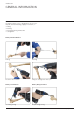
Ensure that the lid of the battery casing is facing towards the scrubbed person (Fig. 3). Position the sterile cover securely on top of the battery casing (Fig. 4). Notes: • The sterile cover helps to guide the battery into the battery casing and prevents contamination of the sterile casing by the nonsterile battery. • Sterilize the sterile cover after each use to ensure aseptic conditions when inserting the nonsterile battery into the sterile battery casing.
Operating Instructions Battery Pack (battery casing with inserted battery) Circulating person Insert the non-sterile battery through the sterile cover into the battery casing (Fig. 5a). Press down on the battery to ensure it is fully seated (Fig. 5b). Circulating person Note: The shape of the battery ensures that it is in serted with the correct pole alignment. The circulat ing person must not touch the outside of the battery casing. Remove the sterile cover from the battery casing (Fig. 6).
Scrubbed person Close the battery casing (Figs. 7a and 7b). Both battery casing locks must be pressed simultaneously to close the lid of the battery casing (Fig. 7a). Note: Ensure that both battery casing locks engage and that the lid of the battery casing is closed pro perly. Always ensure that the lid of the battery cas ing is totally closed before using the system. Precaution: Do not contact the nonsterile battery or the inside of the battery casing in order to avoid contamination.
Operating Instructions Battery Pack (battery casing with inserted battery) Insert the battery pack into the drive unit, ensuring the contacts on the battery pack align with the contacts in the recess of the drive unit (Fig. 8). Press firmly to ensure the battery pack is engaged correctly, and check by pulling lightly downward on the battery pack. Precautions: • For safety reasons, the battery pack can only be in serted fully when it is in the correct orientation.
Removing and disassembling the battery pack Press both release buttons simultaneously on the drive unit to remove the battery pack (Fig. 9). Open the casing by pressing both battery casing locks and remove the battery or hold open the battery casing to allow another person to remove the battery (Fig. 10). Ensure that the battery does not touch the exterior of the battery casing in order to avoid contaminating the battery.
Operating Instructions Battery Pack (battery casing with inserted battery) Charging, storing and using batteries Charging Only use the S ynthes Universal Battery Charger II (05.001.204) to charge the battery. Using a charger that does not originate from Synthes can damage the battery. In order that the BPL II battery can be recognized and charged by the UBC II, a minimum of firmware version 14.0 is required. If necessary, send the charger to a Synthes representative for a firmware update.
Precautions: • Generally, medical power tools will heat up if in constant use. The cool down times should be ob served, see “Duty Cycle” section on page 76, in or der to prevent the power tool from exceeding its acceptable surface temperature. • In case of cell leakage, do not allow the leaking fluid to come into contact with skin or eyes. In case of contact, wash the affected area with copi ous amounts of water and seek medical advice.
Operating Instructions BATTERY REAMER/DRILL II (530.705) For clockwise rotation, turn the mode switch to the “FWD” position. For counterclockwise rotation, turn the mode switch to the “REV” position. The single variable-speed trigger allows control of the speed from 0 to the maximum rpm. Maximum torque and speed vary, depending on the attachment (see pages 23 ff). Ensure that the correct attachment is used for each operation in terms of speed and torque.
Operating Instructions ATTACHMENTS FOR BATTERY REAMER/DRILL II Instrument 530.705 Battery Reamer/Drill II Precaution: To prevent injuries, the mode switch of the drive unit should always be in the “OFF” posi tion when inserting or removing attachments and cutting tools. Please observe the safety instructions and warnings stated in the instructions when working with attachments. Only use original Synthes attachments.
Operating Instructions Attachments for Battery Reamer/Drill II Color marking on the attachments Some rotating attachments are available in two different speeds for drilling and reaming, respectively. The attachments are marked accordingly (Figs.
The following notes apply to all attachments. Notes: • Always turn the mode switch to “OFF” position when inserting/removing attachments and cutting tools. • If the attachment does not engage properly then ro tate the attachment gently until the drive shaft en gages. • After inserting a cutting tool, always check that it is properly engaged by pulling it. • Only use original S ynthes attachments and cutting tools.
Operating Instructions Attachments for Battery Reamer/Drill II Drill Chuck with Key, Drill Speed (530.730) Drill Chuck with Key, Ream Speed (530.732) Maximum speed: Drilling: approx. 930 rpm Reaming: approx. 340 rpm Drill Chuck (530.730) Maximum torque: Drilling: approx. 6.0 Nm Reaming: approx. 15.0 Nm Cannulation: Drilling: B 3.2 mm Reaming: B 4.0 mm Drill Chuck (530.732) Accept round and triangular shafts up to B 7.3 mm Technical data is subject to tolerances.
Drill Chuck, Keyless, Drill Speed (530.731) Maximum speed: approx. 930 rpm Maximum torque: approx. 6.0 Nm Cannulation: B 3.2 mm Accepts round and triangular shafts up to B 7.3 mm Technical data is subject to tolerances. Insert instrument Open the chuck jaws by holding on to the retaining ring and manually turning the chuck (Fig. 1). Figure 1 Insert the instrument shaft into the opened chuck. Close the chuck by holding on to the retaining ring and manually turning the chuck in the opposite direction (Fig.
Operating Instructions Attachments for Battery Reamer/Drill II AO/ASIF Quick Coupling for drill bits, Drill Speed (530.750) Maximum speed: approx. 930 rpm Maximum torque: approx. 6.0 Nm Cannulation: B 2.0 mm Accepts cutting tools and instruments with an AO/ASIF quick coupling fitting Technical data is subject to tolerances. Insert instrument Introduce the instrument into the attachment, then push and turn the instrument until it locks in place (Fig. 1).
Quick Coupling for DHS/DCS Triple Reamers, Drill Speed (530.760) Maximum speed: approx. 930 rpm Maximum torque: approx. 6.0 Nm Cannulation: B 3.2 mm Accepts cutting tools and instruments with a large quick coupling fitting. These include DHS/DCS triple reamers, large quick coupling screwdriver shafts, large quick coupling cannulated drill bits for Synthes intramedullary nailing systems and the Synthes Reamer/Irrigator/Aspirator (RIA) system. Technical data is subject to tolerances.
Operating Instructions Attachments for Battery Reamer/Drill II Drilling/Reaming Attachments Maximum speed: Drilling: approx. 930 rpm Reaming: approx. 340 rpm Maximum torque: Drilling: approx. 6.0 Nm Reaming: approx. 15 Nm Cannulation: Drilling: B 3.2 mm Reaming: B 4.0 mm Technical data is subject to tolerances. Hudson Quick Coupling (530.792), Drill speed Hudson Quick Coupling (530.782), Ream speed Accept cutting tools and instruments with a Hudson fitting. Trinkle Quick Coupling, modified (530.
Trinkle Quick Coupling (530.794), Drill speed Trinkle Quick Coupling (530.784), Ream speed Accept cutting tools and instruments with a Trinkle fitting. Trinkle QC XXL, modified (530.795), Ream speed Accepts cutting tools and instruments with a large, tapered, modified Trinkle fitting. Insert instrument Pull back the collar of the attachment and insert the instrument, turning it slightly to align the instrument (Fig. 1). Release the collar, pulling lightly on the instrument to ensure it is secure.
Operating Instructions Attachments for Battery Reamer/Drill II AO/ASIF Quick Coupling for Reamers, Reaming Speed (530.780) Maximum speed: approx. 340 rpm Maximum torque: approx. 15 Nm Cannulation: B 4.0 mm Accepts cutting tools and instruments with an AO reaming fitting, including intramedullary reaming shafts with the AO reaming fitting. Technical data is subject to tolerances. Insert instrument Insert the instrument into the attachment and turn it until it locks in place.
Quick Coupling for Kirschner Wires and for Pins, Drill Speed (530.791) Maximum speed: approx. 930 rpm Maximum torque: approx. 6.0 Nm Cannulation: B 4.0 mm Allows insertion and removal of Kirschner wires and guide pins with diameters from B 1.5 mm to 4.0 mm, in any length (as shown on page 3). Technical data is subject to tolerances. Please refer to page 34 for instructions on insertion and removal of Kirschner wire/guide pin.
Operating Instructions Attachments for Battery Reamer/Drill II Insert Kirschner wire/guide pin into attachment Set the appropriate diameter range on the attachment adjusting sleeve. To adjust, push in the head of the attachment (1) and then turn to the required diameter (2) (Fig. 1). Insert the wire/pin into the front of the attachment (Fig. 2). Adjust the working length by pulling in the wire/ guide pin. Push (1) Figure 1 Note: The attachment is springloaded to prevent the wire/pin from falling out.
Quick Coupling for Pins, Drill Speed (530.796) Maximum speed: approx. 930 rpm Maximum torque: approx. 6.0 Nm Cannulation: B 3.2 mm Dedicated attachment to fix knee replacement cutting blocks with a pin (as shown on page 3). Allows insertion and removal of B 3.2 mm guide pins with round, triangular and flat shafts. Technical data is subject to tolerances. Insert guide pin into attachment Insert a B 3.2 mm guide pin into the front of the attachment (Fig. 1).
Operating Instructions Attachments for Battery Reamer/Drill II Radiolucent Drive (511.300) and Adapter for Radiolucent Drive (530.741) Maximum speed: approx 1100 rpm Assemble Radiolucent Drive Insert the Adapter for Radiolucent Drive into the Battery Reamer/Drill II. Slide the Radiolucent Drive over the Adapter and twist until the drive shaft engages. Maximum torque: approx. 1.3 Nm Rotate the Radiolucent Drive into the desired working position. Support the drive with your free hand.
Insert drill bits 1. Pull the ring on the Radiolucent Drive forward and push the drill bit into the coupling as far as it can go while rotating it slightly (Fig. 1). 2. Engage the ring on the attachment back to fix the drill bit. Check if the drill bit is seated correctly by gently pulling on it. Remove drill bits To remove the drill bit execute step 1 and 2 above in reverse order.
Operating Instructions Attachments for Battery Reamer/Drill II Notes: • Grip the coupled Radiolucent Drive tightly when switching on the power tool, particularly if the power tool is held face down. • Only special 3-flute spiral drill bits can be used. Your Synthes representative will be glad to pro vide you with additional information on which drill bits can be used. • Handle the Radiolucent Drive with great care. Do not allow contact between the drill bit and the medullary nail.
Operating Instructions BATTERY OSCILLATOR II (530.710) To operate the drive unit, turn the mode switch to the “ON” position. The single variable-speed trigger allows control of the oscillating frequency from 0 to 12 000 oscillations per minute. When the trigger is released, the power tool stops immediately. Ensure the drive unit is running prior to contacting the bone.
Operating Instructions Battery Oscillator II (530.710) Insert saw blade Fully open the saw blade coupling by turning the locking knob. Insert an oscillating saw blade into the coupling. Turn the locking knob in the opposite direction to secure the saw blade. Tighten the locking knob (Fig. 1). Adjust sawing plane Pull the sliding sleeve back and rotate the saw head to adjust the sawing plane (adjustable through 360° in 45° increments, Fig. 2).
Remove saw blade Open the saw blade coupling fully by twisting the locking knob and remove the oscillating saw blade (Fig. 3). Instructions for handling saw blades Synthes recommends using a new saw blade for each operation to ensure that the saw blade is optimally sharpened and clean.
Operating Instructions BATTERY RECIPROCATOR II (530.715) To operate the drive unit, turn the mode switch to the “ON” position. The single variable-speed trigger allows control of the reciprocating frequency from 0 to 14 000 oscillations per minute. When the trigger is released, the tool stops immediately. Ensure the drive unit is running prior to contacting the bone.
Insert saw blade Insert a reciprocating saw blade into the coupling and push until the saw blade locks in place (Fig. 1). Lightly pull the saw blade to ensure it is properly seated. Adjust sawing plane Pull the sliding sleeve back and rotate the saw head to adjust the sawing plane (adjustable through 360° in 45° increments, Fig. 2). Release the sliding sleeve and turn the saw head slightly until it locks in place.
Operating Instructions Battery Reciprocator II (530.715) Instructions for handling saw blades Synthes recommends using a new saw blade for each operation to ensure that the saw blade is optimally sharpened and clean.
Care and Maintenance GENERAL INFORMATION Power tool units and attachments are frequently exposed to high mechanical loads and shocks during use and should not be expected to last indefinitely. Proper handling and maintenance help extend the useful life of surgical instruments. Gentle care and maintenance with proper lubrication can substantially increase the reliability and life of the system components and reduce the risk of malfunction or harm to the user and patient.
Care and Maintenance General Information Unusual Transmissible Pathogens Surgical patients identified as at-risk for Creutzfeldt- Jakob disease (CJD) and related infections should be treated with single-use instruments. Dispose of instruments, power tools and attachments used, or suspected to have been used, on a patient with CJD after surgery by incineration and/or follow current national recommendations.
Care and Maintenance PREPARATION PRIOR TO CLEANING Disassembly Before cleaning, remove all instruments and attachments from the power tool. Remove the battery casing from the handpiece and then remove the battery itself. To clean the battery and the charger, wipe them off with a clean, soft and lint-free cloth dampened with deionized water (Figs 1 and 2).
Care and Maintenance MANUAL CLEANING INSTRUCTIONS 1. Remove debris Rinse the device under running cold tap water for a minimum of 2 minutes. Use a sponge, soft lint-free cloth or soft-bristled brush to assist in removing gross soil (Fig. 1). For cannulations of the handpiece and attachments, the cleaning brush (516.101) shown below should be used. Notes: • Do not use pointed objects for cleaning.
3. Spray and wipe Spray and wipe the device using a neutral pH enzymatic solution for a minimum of 2 minutes (Fig. 2). Follow the enzymatic detergent manufacturer’s directions for correct temperature, water quality (i.e. pH, hardness) and concentration/dilution. 4. Clean with detergent Clean the device manually under running warm water using an enzymatic cleaner or detergent for a minimum of 5 minutes. Manipulate all moving parts under running water.
Care and Maintenance Manual Cleaning Instructions 5. Rinse with tap water Rinse the device thoroughly using cool to lukewarm running water for a minimum of 2 minutes. Use a syringe or pipette to flush lumens and channels. Actuate joints, handles and other movable device features in order to rinse thoroughly under running water. 6. Visually inspect device Inspect the cannulations, sliding sleeves, attachment release rings, etc. for visible soil. Repeat steps 1–6 if visible soil remains. 7.
Care and Maintenance AUTOMATED CLEANING INSTRUCTIONS WITH MANUAL PRE-CLEANING Notes: • Manual precleaning prior to automated cleaning is important to ensure cannulations and other dif ficult to access areas are clean. • Alternative cleaning procedures other than in the procedure described below (including manual pre cleaning) have not been validated by Synthes. 1. Remove debris Rinse the device under running cold tap water for a minimum of 2 minutes.
Care and Maintenance Automated Cleaning Instructions with Manual Pre-cleaning 2. Manipulate moving parts Manipulate all moving parts such as triggers, sliding sleeves, attachment release rings, saw blade coupling and switches under running tap water to loosen and remove gross debris. 3. Spray and wipe Spray and wipe the device using a neutral pH enzymatic solution for a minimum of 2 minutes (Fig. 2). Follow the enzymatic detergent manufacturer’s directions for correct temperature, water quality (i.e.
7. Load S ynthes Washing Basket Please use the specially designed tray for machine washing as supplied by Synthes (68.001.620, 68.001.625). Follow the numbered loading plans as shown on pages 54 and 55. Ensure that the attachments are positioned in an upright position as shown and fully opened. This will ensure that the water can flow off any surfaces. Notes: • A lid (68.001.602, 68.001.604) is available for the washing basket. This can be used for sterilization, but is not required for machine washing.
Care and Maintenance Automated Cleaning Instructions with Manual Pre-cleaning 68.001.620 Washing Basket Full size ¹⁄¹ 530.705 Battery Reamer/Drill II or 530.605 Battery Reamer/Drill 530.710 Battery Oscillator II, or BPL II: 530.705 Battery Reamer/Drill II, or 530.715 Battery Reciprocator II BPL: 530.605 Battery Reamer/Drill, or 530.610 Battery Oscillator, or 530.615 Battery Reciprocator 510.191 Key for Drill Chuck (530.730 and 530.732) Two spots for 530.790, 530.791, 530.
68.001.625 Washing Basket size ½ 530.690 Battery Casing 530.715 Battery Reciprocator II, or BPL II: 530.705 Battery Reamer/Drill II, or 530.710 Battery Oscillator II BPL: 530.605 Battery Reamer/Drill, or 530.610 Battery Oscillator, or 530.615 Battery Reciprocator 68.001.604 Lid for Washing Basket size ½ 530.660 Sterile Cover 68.001.625 and 68.001.
Care and Maintenance Automated Cleaning Instructions with Manual Pre-cleaning 8. Automated cleaning cycle parameters Note: The washer/disinfector should fulfill require ments specified in ISO 15883.
Care and Maintenance LUBRICATION To ensure a long service life and smooth operation, it is necessary that the accessible moving parts of the handpiece, battery casing and attachment are lubricated after each use with 1 drop of S ynthes Special Oil (519.970). Spread the oil by moving the components. Wipe off excess oil with a cloth. Failing to lubricate the parts will lead to damage and malfunction, increasing the risk of harm to the user and patient.
Care and Maintenance Lubrication Battery Reamer/Drill II (530.705) The following individual parts must be lubricated with 1 drop of Synthes Special Oil (519.970): 1 Attachment release ring (Figs. 1a and 1b) 2 Trigger shaft 3 Rear end of the cannulation (Fig. 3) 1 1 3 Turn the attachment release ring clockwise and insert 1 drop of Synthes Special Oil (519.970) as shown in figure 1a. Then turn the release ring several times. 2 Insert 1 drop of Synthes Special Oil (519.
Battery Oscillator II (530.710) The following individual parts must be lubricated with 1 drop of Synthes Special Oil (519.970): 1 Saw blade coupling 2 Locking knob for the saw blade quick coupling 3 Sliding sleeve for positioning the saw blade (Figs. 1a and 1b) 4 Trigger shaft 3 1 2 Pull the sliding sleeve back and put 1 drop of Synthes Special Oil (519.970) on the exposed area (Fig. 1a). Then push the sleeve forward and put 1 drop of oil on the other exposed area (Fig. 1b).
Care and Maintenance Lubrication Battery Reciprocator II (530.715) The following individual parts must be lubricated with 1 drop of Synthes Special Oil (519.970): 1 Saw blade coupling 2 Sliding sleeve for positioning the saw blade (Figs. 1a and 1b) 3 Trigger shaft 2 2 1 Pull the sliding sleeve back and put 1 drop of Synthes Special Oil (519.970) on the exposed area (Fig. 1a). Then push the sleeve forward and put 1 drop of oil on the other exposed area (Fig. 1b).
Lubricating the battery casing (530.690) Place oil on the complete inside edge of the battery casing and distribute it evenly. Open and close the lid several times to lubricate the sealing. Wipe off excess oil with a cloth (Fig. 1). Battery Casing for Battery Power Line II (530.
Care and Maintenance Lubrication Lubricating the attachments After each use lubricate all moving parts of the attachment with 1 drop of Synthes Special Oil (519.970) (Figs. 1a and 1b). Spread the oil by moving the components. Wipe off excess oil with a cloth. 1 1 Insert 1 drop of Synthes Special Oil (519.970) in the gap between the seal ring and shaft of the attachment coupling (Fig. 2a and 2b).
Care and Maintenance INSPECTION AND FUNCTION TEST Instructions Visually inspect for damage and wear. Check the handpiece controls for smooth operation and function. All movable parts should be moving smoothly. Check that the triggers do not remain blocked in the handpiece when pressing on them. Check that no residuals prevent the movable parts from moving smoothly. Check the release ring of the handpiece and attachments for smooth operation, and check for function together with cutting tools.
Care and Maintenance PACKAGING, STERILIZATION AND STORAGE Packaging Put cleaned and dry products into their proper places in the Synthes Vario Case (689.202, Figs. 1a–1d) or the Synthes Washing Baskets (68.001.620, 68.001.625, Figs. 2a and 2b). Additionally, use an appropriate sterilization wrap or re-usable rigid container system for sterilization, such as a Sterile Barrier System according to ISO 11607.
Sterilization Precaution: • Remove batteries from battery casings. Do not sterilize batteries as they will be damaged and no longer function. Notes: • If the Vario Case (689.202) is sterilized in a steril ization wrap, use the lid (689.507). • If the Washing basket (68.001.620, 68.001.625) is sterilized in a sterilization wrap, use the lid (68.001.602, 68.001.604). • If the Vario Case (689.202) is sterilized in a rigid container, the lid (689.507) is not required. • If the Washing basket (68.001.620, 68.
Care and Maintenance Packaging, Sterilization and Storage Storage Storage conditions for products labeled “STERILE” are printed on the packaging label. Packaged and sterilized products should be stored in a dry, clean environment, protected from direct sunlight, pests, and extremes of temperature and humidity. Use products in the order in which they are received (“firstin, first-out principle“), taking note of any expiration date on the label.
Care and Maintenance REPAIRS AND TECHNICAL SERVICE The power tool should be sent to the Synthes office for repair if it is faulty or malfunctions. Contaminated products have to run through the complete reprocessing procedure before being sent to the Synthes office for repair or technical service. To prevent damage during shipping use the original packaging to return devices back to Synthes. If this is not possible, please contact the Synthes a ffiliate.
Care and Maintenance DISPOSAL OF WASTE In most cases, faulty power tools can be repaired (refer to the previous section “Repairs and Technical Service”). Please send devices that are no longer used to your local Synthes representative. This ensures that they are disposed of in accordance with the national application of the respective directive. The device may not be disposed of with household waste. To prevent damage during shipping use the original packaging to return devices back to Synthes.
TROUBLESHOOTING General Problem Possible causes Solution Drive unit does not start No battery in the drive unit Insert charged battery Battery is discharged Charge or replace battery Battery is defect Replace battery Drive unit is defect Send drive unit to Synthes Service Center Drive unit did not cool down after sterilization Allow to cool to room temperature Mode switch is set to «lock» (off position) Set mode switch to ON/FWD/REV No electrical contact between drive unit and battery casin
Troubleshooting Problem Possible causes Solution Visible physical damage on items Battery was accidentally reprocessed Replace battery. Send damaged battery to Synthes Service Center Drive unit, attachment, battery casing, sterile cover was dropped Replace damaged items.
Battery Reamer/Drill II Problem Possible causes Solution Attachments cannot couple to drive unit Coupling is blocked by residue Precaution: Immediately turn mode switch OFF (Lock position). Remove solid particles with pick ups. Clean and lubricate accord ing to care and maintenance guidelines. Attachment coupling is damaged Send damaged attachment to SynthesService Center Coupling is blocked by residue Precaution: Immediately turn mode switch OFF (Lock position).
Troubleshooting Battery Oscillator II Problem Possible causes Solution Saw blade is difficult to couple or cannot be coupled General wear and tear has affected the connection geometry of the saw blade Replace the saw blade Bone and drive unit heat up during surgery The cutting teeth of the saw blade are blunt Replace the saw blade Battery Oscillator II vibrates too intensively Saw blade locking mechanism is not tight Tighten the locking knob on the saw blade quick coupling Problem Possible cau
Attachments and Cutting Tools Problem Possible causes Solution Attachments cannot couple to drive unit Coupling is blocked by residue Precaution: Immediately turn mode switch OFF (Lock position). Remove solid particles with pick ups. Clean and lubricate accord ing to care and maintenance guidelines. Difficulty removing attachments from drive unit Release sleeve for attachments is jammed/blocked by residue Precaution: Immediately turn mode switch OFF (Lock position).
Troubleshooting Problem Possible causes Solution Guide pin cannot be inserted into the front of the Quick Coupling for Pins attachment (530.796) or cannot be grasped Diameter or shaft geometry is unsuitable Quick Coupling for Pins (530.796) allows insertion and removal of B 3.
SYSTEM SPECIFICATIONS The device meets the following standards EN 60601-1/IEC 60601-1/ EN 60601-1-2/IEC 61000-6-1/ IEC 61000-6-2/IEC 61000-6-3 IEC 61000-6-4 Medical electrical devices 10PB With regard to electrical shock, fire and mechanical hazards only in accordance with EN 60601-1 and ANSI/ AAMI ES60601-1 (2005) and CAN/CSA C22.2 No. 60601.
System Specifications Duty Cycle Intermittent operation type S9, according to IEC 60034-1 Xs on Ys off Cycles Drilling and tapping threads 60 sec 60 sec 5 Kirschner wire and pin setting 30 sec 90 sec 5 Reaming 60 sec 60 sec 5 Oscillating Sawing 30 sec 90 sec 5 Reciprocating Sawing 20 sec 120 sec 5 Generally, electrical systems will heat up if in constant use.
Declaration of the emission sound pressure level and the sound power level according to EU Directive 2006/42/EC Measurement of the sound pressure level [LpA] is carried out in accordance with standard EN ISO 11202. Measurement of the sound power level [LwA] is carried out in accordance with standard EN ISO 3746. Sound Power Level (LwA) in [dB(A)] Max. daily exposure time without hearing protection Handpiece Attachment Cutting Tool Sound Pressure Level (LpA) in [dB(A)] Battery Reamer/Drill II* 530.
System Specifications Declaration of vibration emission according to EU Directive 2002/44/EC Vibration emissions [m/s2] tested according to EN ISO 5349-1. Handpiece Attachment Cutting Tool Declaration [m/s2] Max. daily exposure time to reach limit value [2.5 m/s2] Battery Reamer/Drill II* 530.705 Drill/Ream* – 0.22 >8 h >8 h Battery Oscillator II** 530.710 – Saw blade 519.170 4.51 2 h 27 min >8 h – Saw blade 05.002.105 12.1 20 min 1 h 21 min Saw blade 511.905 9.
Electromagnetic Compatibility ACCOMPANYING DOCUMENTS ACCORDING TO IEC 60601-1-2, 2007, CLAUSE 6 Table 1: Emissions Guidance and manufacturer’s declaration – electromagnetic emissions The Battery Power Line (BPL) or Battery Power Line II (BPL II) System is intended for use in the electromagnetic environment specified below. The customer or the user of the BPL or BPL II System should assure that it is used in such an environment.
Electromagnetic Compatibility Accompanying Documents According to IEC 60601-1-2, 2007, Clause 6 Table 2: Immunity (all devices) Guidance and manufacturer’s declaration – electromagnetic immunity The BPL or BPL II System is intended for use in the electromagnetic environment specified below. The customer or the user of BPL or BPL II System should assure that it is used in such an environment.
Table 4: Immunity (not life-supporting devices) Guidance and manufacturer’s declaration – electromagnetic immunity The BPL or BPL II System is intended for use in the electromagnetic environment specified below. The customer or the user of the BPL or BPL II System should assure that it is used in such an environment.
Electromagnetic Compatibility Accompanying Documents According to IEC 60601-1-2, 2007, Clause 6 Where P is the maximum output power rating of the transmitter in watts (W) according to the transmitter manufacturer and d is the recommended separation distance in meters (m). Field strengths from fixed RF transmitters, as determined by an electromagnetic site survey,a should be less than the compliance level in each frequency range.
Table 5: Recommended separation distances (not life-supporting devices) Recommended separation distances between portable and mobile RF communications equipment and the BPL or BPL II System The BPL or BPL II System is intended for use in the electromagnetic environment in which radiated RF disturbances are controlled.
ORDERING INFORMATION Drive units Vario Case and Washing Basket 530.705 Battery Reamer/Drill II 530.710 Battery Oscillator II 530.715 Battery Reciprocator II 689.202 Vario Case size 1/1 for Battery Power Line II, w ithout lid, 689.507 Lid (Stainless Steel), size 1/1, for Vario Case without contents 68.001.620 Washing Basket, Full Size 1/1, for Battery Power Line II Charger, Battery and Accessories for Battery 68.001.602 Lid for Washing Basket, Full Size 1/1 05.001.
Example Battery Power Line II Set – Joint Replacement Instruments Example Battery Power Line II Set – Trauma Quantity Instruments Quantity 05.001.204 Universal Battery Charger II 1 05.001.204 Universal Battery Charger II 1 530.705 Battery Reamer/Drill II 1 530.705 Battery Reamer/Drill II 1 530.710 Battery Oscillator II 1 530.710 Battery Oscillator II 1 530.715 Battery Reciprocator II 1 530.630 Battery for Battery Power Line II 2 530.630 Battery for Battery Power Line II 3 530.
DSEM/PWT/1114/0051 11/14 SE_493813 AA 036.000.198 All rights reserved. This publication is not intended for distribution in the USA. 0123 © DePuy Synthes Power Tools, a division of Synthes GmbH. 2014. Manufacturer: Synthes GmbH Eimattstrasse 3 CH-4436 Oberdorf www.depuysynthes.