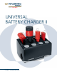
unIVersal baTTery Charger II user‘s Manual
Table of Contents Introduction General Information • Intended use • Compatibility • Abbreviations • Safety precautions • Scope of delivery • Storage and transport • Warranty Description of the Controls 2 2 2 2 3 3 3 3 4 Operating Instructions Starting the System 5 Charging the Battery/Power Module • Charging the battery • Temperature monitoring • Charging new batteries or batteries not recently used • Errors during charging 6 6 7 7 Checking and Refreshing Batteries/Power Module • Battery Power L
Introduction General Information Intended use The Universal Battery Charger II (05.001.204), referred to henceforth as the charger or device, allows the following DePuy Synthes Power Tools batteries to be automatically charged and manually checked: System Handpieces Battery/ Power Module Battery Power Line 530.605 530.620 (14.4 V, NiMH) 530.610 530.615 Battery Power Line II 530.705 530.630 (14.8 V, Li-Ion) 530.710 530.715 Trauma Recon System 05.001.201 05.001.202 (25.
Introduction General Information Safety precautions The device may only be used with the supplied power cord. The device may only be operated on an even, dry surface that is sufficiently strong to hold its weight. 2.5 m Avoid contact with fluids. The device is designed to be operated and stored in closed rooms. Ensure that the device is not operated in the direct vicinity of radiators or other heat emitting devices (please refer to page 23 for details on environmental conditions). 1.5 m 1.
Description of the Controls Front view 1 Charger bays (24) 2 Symbols for battery type 3 ON/OFF display 4 Control display for each charging bay 5 Ventilation holes 1 2 3 4 5 Rear view 6 Ventilation holes 7 ON/OFF power switch 8 Fuses: 225 AT / 250 V 9 Power cord connection 6 7 8 9 Charger bay The device is fitted with four independent charger bays. Each of these has three slots for the following batteries: 10 Battery Power Line and Battery Power Line II batteries (530.620, 530.
Operating Instructions Starting the System Before starting for the first time, ensure that the power switch is set to . The device can only be connected to the power supply using the supplied power cord. Set the power switch to I to turn the device on (Fig. 1). The ON/OFF d isplay light on the front of the device will illuminate (Fig. 2). If the display flashes, the device must be sent in for repair. for a single charger bay Note: If the red display light lights up (Fig.
Operating Instructions Charging the Battery/Power Module Charging the battery Place the battery to be charged in the proper direction into the corresponding slot of an empty charger bay. Only one battery can be charged in each charger bay at a time. All charger bays can, however, be used simultaneously with any combination of battery types. Once the battery types have been identified the charging process starts automatically. This is signalled by the yellow (Fig. 1).
Operating Instructions Charging the Battery/Power Module Temperature monitoring The battery and the charger heat up during the charging process. The ventilation holes should therefore not be covered. flashing If the battery temperature is too high, the yellow charger starts flashing (Fig. 3). To protect the battery, the display device stops charging until the battery has cooled down. Do not remove the battery from the charger if this occurs lights up constantly.
Operating Instructions Checking and Refreshing Batteries/ Power Module Battery Power Line and SBD batteries The charger enables Battery Power Line battery (530.620) and SBD batteries (532.003, 532.033) to be refreshed and checked. It will be indicated if the battery performance is sufficient or if the battery needs to be replaced.
Operating Instructions Checking and Refreshing Batteries/Power Module Completion of the process is indicated as follows: x Green display light (Fig. 3): Battery has been successfully refreshed, checked, and charged. x Red display light (Fig. 4): Either the battery is faulty or performance is insufficient. The battery must be disposed of. The entire process (refreshing and checking battery status) takes around 10 hours and should only be carried out if there is enough time to do so.
Operating Instructions Checking and Refreshing Batteries/Power Module Battery Power Line II and SBD II batteries The charger enables Battery Power Line II and SBD II batteries (530.630, 532.103) to be checked. It will be indicated if the battery performance is sufficient or if the battery needs to be replaced. Due to the very low self-discharging rate of Lithium-based batteries a refresh function is not required. When required, the check function is started manually, as outlined below.
Operating Instructions Checking and Refreshing Batteries/Power Module Completion of the process is indicated as follows: x Green display light (Fig. 7): Battery has been successfully checked and charged. x Red display light (Fig. 8): Either the battery is faulty or performance is insufficient. The battery must be disposed of. The entire process (checking battery status) takes around 3 hours and should only be carried out if there is enough time to do so.
Operating Instructions Checking and Refreshing Batteries/Power Module Trauma Recon System power module To ensure that the Trauma Recon System (05.001.201, 05.001.240) is operating properly, the Trauma Recon System power module (05.001.202) has to be checked at periodical intervals. It will be indicated if the power module performance is sufficient or if the power module needs to be replaced.
Operating Instructions Storing Batteries Immediately recharge batteries and the power module after each use. Any SBD batteries (532.003, 532.033) or Battery Power Line battery (530.620) that are not used should a lways be stored in the activated charger (maintenance charge). This guarantees that the batteries are always fully charged and ready to use. Precautions: x Do not use batteries/power modules that are not fully charged. A partial charge may not be sufficient for the i ntended use.
Operating Instructions Slot Covers Set The Slot Covers Set (05.001.228) consists of three plastic elements which were developed to cover the unused slots of the charger (Fig. 1). A Slot Cover helps to insert a battery or power module much easier into the Universal Battery Charger II because it covers the unused slots of the charger (Fig. 2). Therefore, it prevents the insertion of a battery or power module into the wrong slot. Fig. 1 Fig.
Care and MaInTenanCe Cleaning The device must be unplugged before it is cleaned. occasionally wipe down the device with a dry cloth. If it is very dirty the device can be cleaned with a slightly damp cloth. dry well. do not use solvents. Whenever it is cleaned the device should be checked to ensure it is working properly and is not damaged. Maintenance of the device is not required. If there are any faults, please send the device to the DePuy Synthes Power Tools service department for repair.
Care and Maintenance Repair and Technical Service The device should be sent to the DePuy Synthes Power Tools Service Department for repair if it is faulty or malfunctions. The same applies if the ON/OFF display does not light up or flashes when the device is switched on. To prevent damage during shipping use the original packaging to return devices back to DePuy Synthes Power Tools. If this is not possible, please contact the DePuy Synthes Power Tools representative.
Care and Maintenance Disposal In most cases faulty chargers can be repaired (see previous section “Repair and Technical Service”). The European directive 2002/96/EC on waste electrical and electronic equipment (WEEE) applies to this device. This device contains materials that should be disposed of in accordance with environment p rotection requirements. Please observe national and local regulations. Please send devices that are no longer used to the DePuy Synthes Power Tools Service Department.
Troubleshooting Problem Possible cause Solution ON /OFF display does not light up. Charger is switched off. Switch on power switch. Power cord is not plugged in. Connect power cord to the connection on the charger and plug into the wall socket. Then switch on the power switch on the charger. Power supply is interrupted (e.g. faulty fuse). Check power supply. Replace fuse (2 X 5 AT / 250 V) if necessary. Charger is faulty.
Troubleshooting Problem Possible cause Solution Red display lights up when the charger is switched on before the batteries /power modules are inserted. Charger bay is faulty. Use another free charger bay. Send the charger to the DePuy Synthes Power Tools Service Department for repairs. flashes during the Yellow display charging process. Battery/power module is too hot. Leave battery/power module inserted in the charger bay.
Troubleshooting Problem Possible cause Solution Battery/power module performance is low. Insufficient battery/power module status. Refresh battery (see page 8). Only possible with Battery Power Line battery (530.620) and SBD batteries (532.003, 532.033). Expected battery/power module life is reached. Test battery/power module (see page 8). lights up, replace If the red d isplay battery/power module. Battery/power module is not ready for use. Charge battery/power module until lights up.
System Specifications Device Specifications Dimensions (L2B2H) Weight Operating voltage Operating current Mains rated input Protection class Protection type by casing 310 mm 2 220 mm 2 175 mm 4.8 kg 100 V – 240 V, 50/60 Hz 1.2–2.
System Specifications Minimum Required Firmware Version of UBC II In order that the different battery types can be recognized and charged by UBC II the correct Firmware version is required. The table below outlines the requirements for each battery type. If required, send the charger to the DePuy Synthes Power Tools Service Department for a firmware update.
System Specifications Environmental Conditions Operation Storage Transport Temperature 40 °C 50 °C 60 °C 104 °F 122 °F 140 °F 10 °C –20 °C –29 °C for max.
System Specifications Applicable Standards The device meets the following standards: EN/IEC 60601-1 2nd Edition 10PB Universal Battery Charger II With respect to electrical shock, fire, and mechanical hazards only in accordance with UL 60601-1/CAN/CSA C22.2 No. 601.1 IEC 60601-1-2 IEC 60601-1-4 EN/IEC 60601-1 3rd Edition Universal Battery Charger II With respect to electrical shock, fire, and mechanical hazards only in accordance with ANSI/AAMI ES60601-1 (2005+C1+A2) CSA C22.2 No 60601.
Electromagnetic Compatibility Accompanying Documents in Accordance with EN/IEC 60601-1-2, Clause 5.2.2 Table 1: Emissions Guidelines and manufacturer’s declaration – electromagnetic emissions The DePuy Synthes Power Tools Universal Battery Charger II is intended for use in the electromagnetic environment specified below. The customer or the user of the DePuy Synthes Power Tools Universal Battery Charger II should assure that it is used in such an environment.
Electromagnetic Compatibility – Accompanying Documents in Accordance with EN/IEC 60601-1-2, Clause 5.2.2 Table 2: Immunity (all devices) Guidelines and manufacturer’s declaration – electromagnetic immunity The DePuy Synthes Power Tools Universal Battery Charger II is intended for use in the electromagnetic environment specified below. The customer or the user of the DePuy Synthes Power Tools Universal Battery Charger II should assure that it is used in such an environment.
Electromagnetic Compatibility – Accompanying Documents in Accordance with EN/IEC 60601-1-2, Clause 5.2.2 Table 4: Immunity (not life-supporting devices) Guidance and manufacturer’s declaration – electromagnetic immunity The DePuy Synthes Power Tools Universal Battery Charger II is intended for use in the electromagnetic environment specified below. The customer or the user of the DePuy Synthes Power Tools Universal Battery Charger II should assure that it is used in such an environment.
Electromagnetic Compatibility – Accompanying Documents in Accordance with EN/IEC 60601-1-2, Clause 5.2.2 Table 6: Recommended separation distances (not life-supporting devices) Recommended separation distances between portable and mobile RF communications equipment and the Synthes Universal Battery Charger II The DePuy Synthes Power Tools Universal Battery Charger II is intended for use in the electromagnetic environment in which radiated RF disturbances are controlled.
Batteries/Power Modules Compatible with Universal Battery Charger II Battery for Battery Power Line Product number 530.620 Operating voltage (rated) 14.4 V Battery capacity 2 Ah / 28.8 Wh Battery NiMH Typical charging time <60 min Battery for Battery Power Line II Product number 530.630 Operating voltage (rated) 14.8 V Battery capacity 1.5 Ah / 22.2 Wh Battery Li-Ion Typical charging time <60 min Power Module for Trauma Recon System Product number 05.001.202 Operating voltage (rated) 25.
Batteries/Power Modules Compatible with Universal Battery Charger II Batteries for Small Battery Drive Product number 532.003 Operating voltage (rated) 12 V Battery capacity 0.5 Ah / 6 Wh Battery NiCd Typical charging time <60 min Product number 532.033 Operating voltage (rated) 14.4 V Battery capacity 0.5 Ah / 7.2 Wh Battery NiCd Typical charging time <60 min Battery for Small Battery Drive II Product number 532.103 Operating voltage (rated) 14.4 V Battery capacity 1.2 Ah / 17.
Explanation of Symbols Used Symbols for Operating the Charger Battery is charged. The charger has switched to maintenance charge and checks that the battery is always fully charged and ready to use. Lighting display: the battery is partially charged. The charging process is not completed. Flashing display: the battery is too hot (see page 7). The battery is faulty and has to be replaced (see page 7) or the charger bay is faulty (see page 5).
Explanation of Symbols Used Symbols on the Charger Read the provided instructions for use b efore operating the device. SW-Rev.11.0 2010 /08 /04 Firmware version of UBCII (see page 22) Caution The European directive 2002/96/EC on waste electrical and electronic equipment (WEEE) applies to this device. This device contains materials that should be disposed of in accordance with environment p rotection requirements. Please observe national and local regulations.
Ordering Information Battery charger 05.001.204 Universal Battery Charger II Batteries 530.620 Battery for Battery Power Line, 14.4 V 530.630 Battery for Battery Power Line II, 14.8 V 05.001.202 Power Module for Trauma Recon System 25.2 V 532.003 Battery for SBD/SBD II, 12 V, standard 532.033 Battery for SBD/SBD II, 14.4 V 532.103 Battery for SBD/SBD II, 14.4 V Power cord 05.001.140 Power Cord, three-pole, North America Slot Covers Set 05.001.
Limited Warranty and Disclaimer: Products are sold with a limited warranty to the original purchaser against defects in workmanship and materials. Any other express or implied warranties, including warranties of merchantability or fitness, are hereby disclaimed. Please contact Customer Service for full Warranty statement. WARNING: in the USA, this product has labeling limitations. See package insert for complete information. CAUTION: USA Law restricts these devices to sale by or on the order of a physician.