
Instruction Manual

15405-InstructionSheet
Derale Performance, Los Angeles, CA 800.421.6288 www.derale.com
INSTALLATION INSTRUCTIONS
REMOTE COOLER INSTALL KIT
PART # 15405
KIT CONTENTS
QTY. DESCRIPTION
1 Oil Cooler
1 Sandwich Adapter
1 2 3/4” O-ring
1 Adapter Plate
1 3 ½” O-ring
2 3/8” NPT x 1/2” Barb Fittings
2 1/2” NPT x 1/2” Barb Fittings
10ft 1/2” OEM Spec Hose
5 6” Zip Ties
QTY. DESCRIPTION
4 Hose Clamps
1 3/4-16 Sleeve Nut (Yellow)
1 18mm Sleeve Nut (White)
1 20mm Sleeve Nut (Black)
1 22mm Sleeve Nut (Green)
1 13/16-16 Sleeve Nut (Blue)
1 13/16-16 Sleeve Nut (Red)
4 Mounting Rods
4 Foam Pads
4 Mounting Clips
(Page 1)
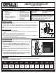
The Oil Cooler can be mounted in multiple locations on your vehicle. Reference Diagram # 1
for possible cooler positions. #1 is the ideal location, #2 is second best and #4 being the last
choice.
The Cooler core will flow in either direction, there is no specified inlet or outlet port.Note:
Diagram #1
TOOLS NEEDED
Standard Screw Driver or
5/16” Nut Driver
Dyke Pliers
Torque Wrench
COOLER MOUNTING
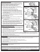
(See Diagram #2)
1. Identify the 4 Mounting Rods, 4 Mounting Clips and 4 1x1 Foam Pads.
2. One by one, Install the 4 Mounting Rods thru the Oil Cooler.
3. Take the 1x1 Foam Pads supplied, peel off the paper lining and slide
them onto the Mounting Rods, sticking them against the Oil Cooler.
4. Take the Cooler Assembly with attached looped hose and hold in the
desired location.
5. Install the 4 Mounting Rods thru the Radiator/Condenser core.
Do not use excessive force when pushing the Mounting Rods
through the Radiator/Condenser. Excessive force could cause damage to
the fins and possibly puncture a tube.
6. Take the Mounting Clips supplied, making sure they are in the correct
direction (Derale writing out) install onto the Mounting Rods and cinch
them until the 1x1 Foam Pads are slightly compressed.
7. Cut off any excess Mounting Rods.
Warning:
7/8” Open End Wrench
11/16” Open End Wrench
1 1/8” Socket
Teflon Tape
Please read these instructions completely before starting the installation.
COOLER LOCATION
When selecting the best location for your vehicle, always consider a location that will
deliver the maximum airflow.
PRE-INSTALLATION
ecure in place using the Hose Clamps. (See Diagram #2)
1. Identify the 1/2” NPT x 1/2” Barb Fittings.
2. Using Teflon Tape or suitable sealant, install the two 1/2” NPT x 1/2” Barb Fittings onto the Oil
Cooler.
3. Identify the 1/2” x 10ft. OEM Spec Hose and Hose Clamps.
4. Slide one hose clamp on each end of the supplied Hose.
5. Using a dab of oil lubricate each end of the hose and install hose onto the 1/2” barb fiittings
now installed on the cooler forming a loop.
6. S
IMPORTANT
In most cases the Factory Oil Filter will work with the supplied sandwich adapter. In some applications where the frame or
exhaust system interferes with the new filter depth we recommend using a shorter filter length.
See chart below for possible filter options.
Diagram #2
Foam Pads
Mounting
Clips
Mounting
Rods
IMPORTANT
This kit is designed to fit all vehicles with engine block
oil filter landings ranging from 2 3/4” to 3 1/2”, which
represents 75% of all vehicles. For vehicles with 2 1/2”
oil filter landings, please visit www.derale.com for
alternative Sandwich Adapter Kits.
FRAM WIX FRAM WIX
THREAD LABEL FILTER FRAM FILTER WIX FILTER FRAM FILTER WIX
SIZE COLOR HEIGHT P/N HEIGHT P/N HEIGHT P/N HEIGHT P/N
3/4-16 YELLOW
13/16-16 BLUE/RED
18mm x 1.5 WHITE
20mm x 1.5 BLACK
22mm x 1.5 GREEN
4.92 PH3600 4.83 51516 3.34 PH3614 3.4 51348
4.94 PH3429 4.83 51045 3.36 Ph3506 3.4 51042
4.94 PH3980 4.83 51036 3.36 PH3387A 3.4 51040
3.47 PH7317 N/A N/A 3.39 PH3593A 3.14 51381
4.94 PH3750 4.57 57026 3.98 PH2 3.43 57060