
Owner manual

15451-InstructionSheet
Derale Performance, Los Angeles, CA 800.421.6288 www.derale.com
INSTALLATION INSTRUCTIONS
ENGINE OIL COOLER KIT
PART # 15451
KIT CONTENTS
QTY. DESCRIPTION
1 Oil Cooler
1 Spin-On Adapter
1 Adapter Plate
1 Ports Up Filter Mount
1 O-ring (Spin-On Adapter)
1 O-ring (Adapter Plate)
1 Snap Ring
1 3/4-16 Filter Nipple
6 1/2” NPT x 1/2” Hose Barb
3 #14 Sheet Metal Screws
QTY. DESCRIPTION
1 3/4-16 Hex Sleeve Nut
1 13/16-16 Hex Sleeve Nut
1 18mm x 1.5 Hex Sleeve Nut
1 20mm x 1.5 Hex Sleeve Nut
1 22mm x 1.5 Hex Sleeve Nut
10ft 1/2” OEM Spec Hose
5 6” Zip Ties
8 Hose Clamps
4 Mounting Rods
4 Foam Pads
4 Mounting Clips
(Page 1)
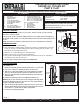
The Oil Cooler can be mounted in multiple locations on your vehicle. Reference Diagram # 1
for possible cooler positions. #1 is the ideal location, #2 is second best and #4 being the last
choice.
The Cooler core will flow in either direction, there is no specified inlet or outlet port.Note:
Diagram #1
TOOLS NEEDED
Standard Screw Driver or
5/16” Nut Driver
Dyke Pliers
Drill and 3/16” Bit
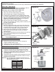
COOLER MOUNTING
(See Diagram #2)
1. Identify the 4 Mounting Rods, 4 Mounting Clips and 4 1x1 Foam Pads.
2. One by one, Install the 4 Mounting Rods thru the Oil Cooler.
3. Take the 1x1 Foam Pads supplied, peel off the paper lining and slide
them onto the Mounting Rods, sticking them against the Oil Cooler.
4. Take the Cooler Assembly with attached looped hose and hold in the
desired location.
5. Install the 4 Mounting Rods thru the Radiator/Condenser core.
Do not use excessive force when pushing the Mounting Rods
through the Radiator/Condenser. Excessive force could cause damage to
the fins and possibly puncture a tube.
6. Take the Mounting Clips supplied, making sure they are in the correct
direction (Derale writing out) install onto the Mounting Rods and cinch
them until the 1x1 Foam Pads are slightly compressed.
7. Cut off any excess Mounting Rods.
Warning:
7/8” Open End Wrench
11/16” Open End Wrench
1 1/8” Socket
Teflon Tape
Please read these instructions completely before starting the installation.
COOLER LOCATION
When selecting the best location for your vehicle, always consider a location that will
deliver the maximum airflow.
PRE-INSTALLATION
ecure in place using the Hose Clamps. (See Diagram #2)
1. Identify the 1/2” NPT x 1/2” Barb Fittings.
2. Using Teflon Tape or suitable sealant, install the two 1/2” NPT x 1/2” Barb Fittings onto the Oil
Cooler, two 1/2” NPT x 1/2” Barb Fittings onto the Spin-On adapter, and two 1/2” NPT x 1/2”
Barb Fittings onto the Ports Up filter mount.
3. Identify the 1/2” x 10ft. OEM Spec Hose and Hose Clamps.
4. Slide one hose clamp on each end of the supplied Hose.
5. Using a dab of oil lubricate each end of the hose and install hose onto the 1/2” barb fiittings
now installed on the cooler forming a loop.
6. S
Diagram #2
Foam Pads
Mounting
Clips
Mounting
Rods
IMPORTANT
This kit is designed to fit vehicles with engine block oil
filter landings ranging from 2 1/2” to 3 1/2”, which
represents 90% of all vehicles.