
Manual

16308-16314-InstructionSheet
INSTALLATION INSTRUCTIONS
ELECTRIC FAN WITH THERMOSTAT KIT
PART # 16308-16316
KIT CONTENTS
QTY. DESCRIPTION
1 Electric Fan Assembly
4 Mounting Rods
4 Mounting Feet
4 1 x 1 Foam Pads
4 Mounting Clips
1 Thermostat Switch & Probe
1 Thermostat Bracket
1 1 1/2” x 1/2” Foam Pad
2 M4-0.7 Philips Head Bolts
QTY. DESCRIPTION
2 #10 Sheet Metal Screws
1 Spool Extra Wire
1 30 Amp Fuse Holder
1 #10 Blue Ring Terminal
1 Blue Wire Tap Connector
3 Blue Butt Connectors
2 Blue Female Connectors
4 4” Zip Ties
Derale Performance, Los Angeles, CA 800.421.6288 www.derale.com
Please read these instructions completely before beginning installation
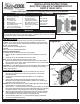
This fan assembly is designed for both PUSHER and PULLER applications.
To change airflow direction from the factory setting, you MUST follow the directions below
or performance will be compromised. (See Diagram #1)
TOOLS NEEDED
Standard Screw Driver
Drill
5/32” Drill Bit
12V Test Light
Wire Stripper
Crimping Tool
Dyke Pliers
PRE-INSTALLATION
Important: All Dyno-Cool Electric Fans come with a product label factory
installed on one end of the fan shroud. Before installation check the product
label to confirm airflow direction. Airflow direction will be shown with an arrow.
8”, 10”, 12” & 14” Fans
Factory setup for PULLER applications
16” Fan
Factory setup for PUSHER applications
Changing airflow direction
To change the airflow direction from the factory setting:
1. Remove the Nut or Clip that holds the electric fan blade onto the motor
shaft.
2. Carefully remove the fan blade from the motor shaft.
Note: This is an interference fit and requires some effort.
3. Flip the fan blade upside down and reinstall onto the motor shaft. Make
sure the roll pin on the motor shaft is aligned with the slot on the fan blade.
4. Reinstall nut or clip on motor shaft.
Important: For Puller applications use the referenced wire colors stated on the
Product Label. For Pusher applications the two wires MUST be reversed to
change airflow direction.
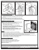
ELECTRIC FAN MOUNTING
1. Take the four supplied Mounting Feet and install them onto the Fan
Shroud in the desired locations around the perimeter of the shroud.
(See Diagram #2)
2. Position the Fan Assembly against the radiator or air conditioning
condenser.
3. Take the four Mounting Rods and carefully install them through the
Mounting Feet and then though EITHER the radiator or air conditioning
condenser. (See Diagram #2 & 3)
Caution: Do not use excessive force when installing Mounting Rods; damage
to the radiator or condenser tubes could occur.
4. Take the four 1 x 1 Foam Pads and remove the paper backing. Now install
them (sticky side toward the core) onto the Mounting Rods now protruding
through the radiator or air conditioning condenser. (See Diagram #3)
5. Take the four Mounting Clips supplied and install them onto the Mounting
Rods. The Mounting Clips can only be used one time, so make sure the
Fan Assembly is in the correct location. (See Diagram #3)
6. Secure Mounting Clips until 1 x 1 Foam Pads are slightly compressed.
7. Cut off any excess Mounting Rod.
Mounting
Rods
Mounting
Clips
1 x 1
Foam
Pads
Diagram #3
Mounting
Feet
Diagram #1
Puller Fan
Pusher Fan
Air Flow
Engine Radiator
Diagram #2
IMPORTANT