
Instruction Manual

18212-18214-18217-InstructionSheet
INSTALLATION INSTRUCTIONS
HIGH OUTPUT 2 SPEED RAD FAN
PART # 18212, 18214, 18217
KIT CONTENTS
QTY. DESCRIPTION
1 High Output RAD Fan
4 Rubber Isolators
4 Foam Pads
QTY. DESCRIPTION
4 Mounting Rods
4 Mounting Clips
Please read these instructions completely before beginning installation
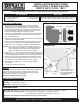
Diagram #1
Puller Fan
Pusher Fan
Air Flow
Engine Radiator
This fan assembly is designed for both PULLER and
PUSHER APPLICATIONS. Note Airflow direction indicated
on product label on the fan housing. (See Diagram #1)
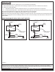
Mounting Clip
Radiator
Foam Pad
Rubber
Isolator
Mounting
Rod
Mounting Rod passes
through radiator. End of
Mounting Rod clipped off
after Mounting Clip is
cinched down.
ELECTRIC FAN MOUNTING
This Electric Fan was designed with a unique symmetrical
design, therefore when switching from a Puller to a Pusher
application there is no flipping blades or reversing wires as on
other reversible models. Simply mount the fan either in front or
back of the radiator making sure the airflow direction arrow on
the fan shroud label is pointed towards the engine.
1. Take the four supplied Rubber Isolators and install them into the
four mounting hole locations on the electric fan on the radiator
side. (See Diagram #2)
2. Position the Fan Assembly against the radiator or air conditioning
condenser in the desired location.
3. Take the four Mounting Rods and carefully install them through
the electric fan mounting holes and then though EITHER the
radiator core or air conditioning condenser. (See Diagram #2)
Do not use excessive force when installing Mounting
Rods; damage to the radiator or condenser tubes could
occur. Mounting Rods should not be installed through
BOTH the radiator and air conditioning condenser.
4. Takethefour1x1FoamPads&removethepaper backing. Now
install them (sticky side toward the core) onto the Mounting Rods
now protruding through the radiator or air conditioning condenser.
5. Take the four Mounting Clips supplied and install them onto the
Mounting Rods. The Mounting Clips can only be used one time,
so make sure the Fan Assembly is in the correct location.
6. Secure Mounting Clips until1x1Foam Pads are slightly
compressed.
7. Cut off any excess Mounting Rod.
Caution:
Derale Performance, Los Angeles, CA 800.421.6288 www.derale.com
Diagram #2
IMPORTANT
WIRING
Important:
Reference Diagrams #7&8onpage 2
The Electric Fan Assembly is built using a High Output
two speed motor. If you choose to operate the fan using both
speeds, two switching devices or a Derale Dual Fan Controller
Part # 16788 or 16789 is recommended.
Black Wire -
Grey Wire -
Brown Wire -
Ground (-)
Low Speed 12V positive (+)
High Speed 12V positive (+)
Important: Low speed must be activated prior to high speed activation
WIRE COLOR DESIGNATIONS
Using High Speed Only -
Using Both Low and High Speeds -
-
Connect both Grey and Brown wires together to the same 12V positive (+) source
Connect Grey wire to Switch #1, 12V positive (+) source.
Connect Brown wire to Switch #2, 12V positive (+) source.
STANDARD WIRING
(Continues on Page 2)