WORKSHOP MANUAL GP1 125-250 c.c.
DERBI - NACIONAL MOTOR, S.A.U., manufacturer of DERBI motorcycles and mopeds, has produced this manual with the aim of documenting and simplifying as much as possible the work you need to do to in dismantling and assembling the GP1 125/250 c.c. The intention is to provide as much assistance as possible to mechanics working for our brand’s dealers and sub-dealers. Due to its constant commitment to improving its products, DERBI - NACIONAL MOTOR, S.A.U.
INTRODUCTION GENERAL INFORMATION GENERAL TECHNICAL DATA RECOMMENDED TOOLS PERIODIC MAINTENANCE Pág. Pág. Pág. Pág. Pág. 1 8 9 30 40 Pág. Pág. Pàg. Pág. Pág. Pág. Pág. Pág. Pág. Pág. Pág. Pág. 64 64 65 65 65 66 66 66 67 68 68 68 Pág. Pág. Pág. Pág. Pág. Pág. Pág. Pág. Pág. Pág. Pág. Pág. Pág. Pág. Pág. Pág. Pág. Pág.
REFITTING THE CLUTCH REFITTING THE DRIVEN PULLEY DRIVE-VELT REMOVING THE DRIVING PULLEY INSPECTING THE ROLLERS CASE REFTTING THE DRIVING PULLEY REFITTING THE TRANSMISSION COVER END GEAR REMOVING THE WHEEL AXLE REMOVING THE HUB BEARING REMOVING THE WHEEL ASXLE BEARING REMOVING THE DRIVEN PULLEY SHAFT BEARING INSPECTING THE HUB SHAFT INSPECTING THE HUB COVER REFITTING THE WHEEL AXLE BEARING REFITTING THE HUB COVER BEARING REFITTING THE HUB BEARING REFITTING THE HUB COVER FLYWHEEL COVER REMOVING THE STATOR FLY
INSPECTING THE PISTON RING REMOVING THE PISTON RING CHOOSING THE GASKET COMPRESSION RATIO VERSION 250 REFITTING THE PISTON RINGS REFITTING THE CYLINDER INSPECTING THE CYLINDER HEAD INSPECTING THE TIMING SYSTEM COMPONENTS INSPECTING THE VALVE SEALINGS INSPECTING THE VALVE HOUSINGS INSPECTING THE VALVES INSPECTING THE SPRINGS AND HALF-CONES REFITTING THE VALVES INSPECTING THE CAMSHAFT REFITTING THE TIMING SYSTEM COMPONENTS REFITTING THE ROCKER - ARMS COVER REFITTING THE INTAKE MANIFOLD REFITTING THE TIMING SY
FORK, SHOCK ABSORBER. ENGINE SUPPORT AND STAND DISMANTLING FRONT SUSPENSION INSPECTING THE FRONT FORKS DISMANTLING INSPECTION SWING-ARM CHECKING THE SWINING ARM EXHAUST BRACKET OVERHAUL REFITTING CENTRE - STAND Pág. Pág. Pág. Pág. Pág. Pág. Pág. Pág. Pág. Pág. 173 175 179 179 180 181 181 182 182 183 Pág. Pág. Pág. Pág. Pág. Pág. 184 185 186 186 188 194 Pág. Pág. Pág. Pág. Pág. Pág. 196 197 198 198 205 205 FRONT WHEEL AND BRAKES REAR WHEEL 125 C.C. REAR WHEEL 250 C.C.
SENSORS AND INDICATORS TURN INDICATORS AND HORN IGNITION CIRCUIT SPARK PLUG STATOR CHECK VOLTAGE REGULATOR CHECK FUSES DISMANTLING THE BATTERY BATTERY - INITIAL CHARGE CAPACITY INSPECTION THE CHARGING CONDITIONS RECHARGING CHARGING SYSTEM Pág. Pág. Pág. Pág. Pág. Pág. Pág. Pág. Pág. Pág. Pág. Pág. Pág. 224 225 226 226 227 227 230 230 232 232 233 234 235 Pág. Pág. Pág. Pág. Pág. Pág. Pág. Pág. Pág. Pág. Pág. Pág. Pág. Pág. Pág. Pág. Pág. Pág. Pág. Pág.
REGULATIONS GU O S This section describes the machine’s general safety and maintenance work rules. SAFETY REGULATIONS S GU O S - In the event of having to carry out work on the engine while this is running, ensure that the area is well ventilated, where possible using extractor fans. Never leave engines running in closed spaces. Exhaust gases are poisonous. Petrol is extremely inflammable and in certain conditions may explode.
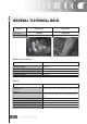
MACHINE ENGINE PREFIX FRAME PREFIX GP1 125 c.c. M434M VTHPS1A1A GP1 250 c.c. M237M VTHPT1A1A DIMENSIONS AND WEIGHT SPECIFICATIONS DESC. / QUANTITY Maximum length 1930 mm. Maximum height 1225 mm. Length between axles 1375 mm. Handlebar width 705 mm. Handlebar height 1085 mm. ENGINE SPECIFICATIONS 9 DESC.
ENGINE SPECIFICATIONS DESC. / QUANTITY Compresion ratio (250) 10,5-11,5: 1 Keihin Carburettor (125 - 250) CVEK-30 Walbro Carburettor (125) WVF 7G* 0 29 Walbro Carburettor (250) WVF-7S* Idle speed 1650 ±50 r.p.m. Adjustment CO 3,8 ± 07 Air filter Sponge-type damped eith a 50% for filters. Oil - 50% unleaded petrol misture Starter system Electric starter motor Lubrication Engine lubrication with geared twin-screw pump (inside the oil sump) coomanded by chain and double paper net filter.
ELECTRICAL SYSTEM ELECTRICAL COMPONENTS SPECIFICATIONS DESC. / QUANTITY Ignition type Electronic with capacitive discharge (CDI) and variable advance with separate HT coil. Ignition advance (before T.D.C) 125 10°±1° at 2000 r.p.m. - 34°±1° at 6000 r.p.m. Ignition advance (before T.D.C) 10° ± 1 at 2000g/min. 28° ± 1 at 6500 g/min.
WHEELS AND TYRES SPECIFICATIONS DESC. / QUANTITY Front wheel rim Aluminium alloy Rear wheel rim In light alloy Front tyre 120 / 70 x 14” Rear tyre 120 / 60 x 14” Tyre pressure front wheel (cold) 1,9 bar Tyre pressure rear wheel (cold) 2,0 bar Tyre pressure rear/front wheel (driver and 2,0 / 2.2 bar passenger). (cold) N.B. CHECK AND ADJUST TYRE PRESSURE WITH TYRES AT AMBIENT TEMPERATURE. ADJUST PRESSURE ACCORDING TO THE WEIGHT OF THE RIDER AND ACCESSORIES.
Flowing through the hole shown in the figure, the air reaches the second filter, «B», At this point, the tiltered air enters the membrane device, so to be channelled towards the head. Flowing through a rigid pipe, flanged to the head, the secondary air reaches the exhaust duct thus providing oxygen addition to the unburnt gases just before they enter the cataiytic converter. The efficiency ofthe catalyzing process is therefore increased.
The working principie ofthe SAS for Quasar 250 cc Euro 2 engines is entirely similar to the SAS employed on 2-stroke engines. The main differences are the following: Secondary air enters directly into the exhaust duct on the cylinder head, instead of entering through the exhaust pipe as in two-stroke engines. The reed valve found on 2-stroke engines is here replaced by a membrane.
CARBURATTOR HEIHIN Version 125 SPECIFICATION DESC. / QUANTITY Depresione type CVEK30 Printing on the body CVK Device CUT-OFF Not present Max. jet 105 Minimum jet 35 Max. air jet 70 Minimum air jet 130 Idle mixture adjusment screw initial opening 2 ±1/4 Conical pin Ø 2,450 Emulsifier nozzle Ø 2,8 Starter air jet Ø 1,5 Starter jet 42 Starter device resistance ~20 Venturi choke Ø 29 Throttle valve Ø 30,5 Choke maximum cone Ø 47 CARBURETTOR WALBRO SPECIFICATION DESC.
CARBURADOR WALBRO SPECIFICATION DESC. / QUANTITY Starter jet 50 Starter pin diameter Ø 1,78 Starter device resistance ~ 40Q Choke Ø 29 (30,3x27,0) Throttie valve Ø 33 Choke máximum cone Ø 48,0 CARBURATTOR HEIHIN Version 250 SPECIFICATION 16 DESC.
CARBURATTOR WALBRO Version 250 SPECIFICATION DESC.
CHASSIS TIGHTENING TORQUES DESCRIPTION M8X125 8.8 FRONT FRAME-CHASSIS SECUR.DEVICE M8X125 8.8 SUBCHASSIS-CHASSIS SEC.DEVICE M10x150 12.9 TOP SHOCK ABSOR.-CHASSIS SEC.DEVICE M10x150 12.9 BOTTOM SHOCK ABSOR.-ENG. SEC.DEV. M14x200 8.8 FRONT ENG. SUPPORT-CHASSIS SEC.DEV. M10X150 8.8 REAR ENG.SUPP-FRONT ENG.SUPP. SEC.DEV. M10X150 8.8 ENGINE-REAR SUPP. SEC.DEV. M8X125 8.8 ENGINE SUPP. SILENTBLOC CLAMP SEC.DEV. M8X125 8.8 SHOCK ABSORBER SUPP. SEC.DEV. M8X125 12.9 SHOCK ABSOR. SUPP. TO CRANKCASE SEC.DEV.
EXAUST PIPE NAME TORQUE IN Nm Screw clamping manifold to silencer 15,5 ÷ 18,5 Screw clamping heat shield to silencer 5÷6 Exhaust gas intake screw 22 ÷ 26 Screw fixing silencer support arm to crankcase 33 ÷ 41 Exhaust pipe/support bracket fixing screw. 27 ÷ 30 Exhaust pipe/cylinder head fixing nut.
CYLINDER HEAD NAME TORQUE IN Nm Tappet adjustment lock nut 6÷8 Timing chain tightener sliding block screws 10 ÷ 14 Start up mass bell screws 11 ÷ 15 M6 central screw fastening washers on 11 ÷ 15 cam shaft (125 cc) Timing beit tightener support screw 11 ÷ 13 Timing beit tightener central screw 5÷6 Camshaft retain píate screw 4÷6 TRANSMISSION NAME TORQUE IN Nm Beit support roller screw 11 ÷ 13 Clutch assembly nut on driven pulley 45 ÷ 50 Driving pulley screw 75 ÷ 83 Transmission cover
ENGINE CRANKCASE AND SHAFT NAME TORQUE IN Nm Engine crankcase inside head screws (transmission side half shaft) 4÷6 Engine crankcase coupling screws 11 ÷ 13 Starter motor screws 11 ÷ 13 Crankcase timing cover screws 3,5 ÷ 4,5 COOLING NAME TORQUE IN Nm Water pump impeller cover 3÷4 Water pump impeller drive joint screw 3÷4 Thermostat cover screws 3÷4 (°) Apply threadlocking LOCTITE médium, type 242.
OVERHAUL DATA ASSEMBLY CLEARANCES CYLINDER - PISTON ASSY CATEGORIES COUPLING 125 PLAY INITIALS CYLINDER PISTON PLAY ON FITTING Cylinder 57+0,025±0,003 A 56,997 ÷ 57,004 56,945 ÷ 56,952 0,045-0,059 Cylinder 57+0,025±0,003 B 57,004 ÷ 57,011 56,952 ÷ 56,959 0,045-0,059 56,959±0,014 C 57,011 ÷ 57,018 56,959 ÷ 56,966 0,045-0,059 NAME Piston Piston 56,959±0,014 D 57,018 ÷ 57,025 56,966 ÷ 56,973 0,045-0,059 Cylinder first uprat.
COUPLING CATEGORIES ENGINE 250 NAME PLAY INITIAL CYLINDER PISTON PLAY ON FITTING Cylinder 72+0,018±0,010 A 71,990 ÷ 71,997 71,953 ÷ 71,960 0,030-0,044 Cylinder 72+0,018±0,010 B 71,997 ÷ 72,004 71,960 ÷ 71,967 0,030-0,044 Piston 71,967±0,014 C 72,004 ÷ 72,011 71,967 ÷ 71,974 0,030-0,044 Piston 71,967±0,014 D 72,011 ÷ 72,018 71,974 ÷ 71,981 0,030-0,044 PISTON RINGS UPRATING TABLE ENGINE 125 NAME 23 DESCRIPTION DIMENSIONS INITIALS QUANTITY Compression lining 57 x 1 A 0,
OVERSIZES ENGINE 250 NAME DESCRIPTION DIMENSIONS INITIALS QUANTITY Compression lining 72 x 1,5 A 0,15 ÷ 0,30 Scraper ring lining 72 x 1 A 0,20 ÷ 0,40 Scraper ring lining 72 x 2,5 A 0,20 ÷ 0,40 CRANKCASE - CRANKSHAFT - CONNECTING ROD CRANKCASE - DRVING SHAFT - BENCH HALF BEARING NAME 24 DESCRIPTION DIMENSIONS INITIALS QUANTITY Half crankshaft bearing Type A -red 1,970 ÷ 1,973 Half crankshaft bearing Type B - blue 1,973 ÷ 1,976 Half crankshaft bearing Type C - yellow 1,976 ÷ 1
FITTING CLEARANCE Driving shaft/case axial clearance: Standard clearance 0,15 ÷ 0,40mm (cold engine).
SLOT PACKING SYSTEM Characteristics Compresion ratio - 125cc verion Rc: 11,50÷13:1 The length «A» to be measured refers to the pistón protrusion. It indicates the amount by which the surface formed by the pistón crown tops the surface formed by the upper parí of the cylinder. The more the pistón descends into the cylinder, the less the base gasket to be applied (to recover the compression ratio) will be and vice versa. N.B.
SLOT PACKING SYSTEM Characteristics Compresion ratio - 125cc verion Re: 11,50÷13:1 The length «A» to be measured refers to the pistón protrusion. It indicates the amount by which the surface formed by the pistón crown tops the surface formed by the upper part of the cylinder. The more the pistón descends into the cylinder, the less the base gasket to be applied (to recover the compression ratio) will be and vice versa. N.B.
SISTEMA DE MONTAJE DE ESPESORES MEASUREMENT (A) (WITH PISTON AT T.D.C.) Características Técnicas Relación de compresión versión 250 Re: 10,5-11,5 NOTE MOUNT ACCORDING TO THE MEASUREMENT (A) OBTAINED NOTE MEASUREMENT (A) MUST BE TAKEN WITHOUT TRIM MOUNTED BETWEEN THE CASING AND THE CYLINDER, AFTER HAVING PUT THE COMPARATOR TO ZERO, WITH ITS SUPPORT, ON A FLAT PLANE. N.B.
OVERSIZES OVERSIZES ENGINE NAME DESCRIPTION DIMENSION INITIALS QUANTITY Compression lining 1° greater 57,2 x 1 A 0,15 ÷ 0,30 First uprated scraper ring lining 57,2 x 1 A 0,10 ÷ 0,30 First uprated scraper ring lining 57,2x2,5 A 0,15 ÷ 0,35 Second uprated compression lining 57,4 x 1 A 0,15 ÷ 0,30 Second uprated scraper ring lining 57,4 x 1 A 0,10 ÷ 0,30 Second uprated scraper ring lining 57,4 x 2,5 A 0,15 ÷ 0,35 Third uprated compression lining 57,6 x 1 A 0,15 ÷ 0,30 Third up
PPREPARATION FOR REMOVAL AND DISMANTLING 1. Remove all the dirt, grime, dust and other foreign material before removing and dismantling. 2. Use properly cleaned tools and equipment. See “SPECIAL TOOLS”. 3. On dismantling the motorcycle, always keep paired parts together. This includes gears, cylinders, pistons and other parts submitted to natural wear in pairs. Paired parts must always be reassembled or replaced together. 4.
REPLACEMENT C PARTS S 1. Use only genuine DERBI spare parts. For all lubrication tasks use oils and greases recommended by DERBI. Other makes make seem similar in their function and appearance, but are inferior in quality. SEALS, RETAINING RINGS AND O-RINGS 1. Replace all seals, retaining rings and O-rings when servicing the engine. All surfaces receiving seals, retaining ring edges and O-rings must be cleaned. 2. Apply oil to all paired parts and bearing during reassembly.
LOC OCKING G RINGS GS 1. Examine all the locking rings carefully before fitting. Always replace the gudgeon pin circlips after every use. Replace distorted locking rings. On fitting a locking ring (1), ensure that the sharp edge (2) is on the opposite side to the force to be applied to it. See the figure on the side, (4) Axle. SPECIAL TOOLS 1. The following special tools are needed for assembly and for complete and exact adjustments.
STORES CODE DESCRIPTION 020412Y 15mm guide 020335Y Magentic stand and comparator 020565Y Compass flywheel stop spanner 020439Y 17mm guide 020359Y 42 x 47mm hub bearing fitting adaptor 33 020363Y 20mm guide 002095Y Engine support 008564Y Flywheel extractor 020434Y Oil presure gauge connection IMAGE
STORES CODE 34 DESCRIPTION 020382Y011 Bushing (valve remover) 020424Y Driven pulley roller casing drift 020431Y Valve oil seal extractor 020193Y Oil pressure gauge 020306Y Valve sealing ring drift 020360Y 52 x 55mm adaptor 020364Y 25mm guide 020375Y Adapter 28 x 30mm IMAGE
STORES CODE DESCRIPTION 020376Y Handle for punches 020444Y Driven half pulley spring compressor tool 020330Y Stroboscopic gun fot two-and four-stroke engines 001467Y035 Bell 020368Y Driving pulley stop wrench 020319Y Immobilizer control test 020287Y Piston band clamps (engine 125 c.
STORES CODE DESCRIPTION 020262Y Crankcase detachment plate 020430Y Pin retainers installation tool (engine 125cc) 020428Y Piston position check support 020426Y Piston fitting fork 020425Y Flywheel-side oil guard punch 020423Y Driven pulley stop key 020414Y 28 mm guide - Hub bearing asembly 020393Y Piston band clamps (Engine 200-250cc) 36 IMAGE
STORES CODE 020382Y DESCRIPTION Tool for removing valve cotters equipped with part 012 020455Y 10mm guide 020442Y Pulley stop wrench 020440Y Water pump overhaul tool 020329Y Pump 020357Y 32 x 35 mm adaptor 020409Y Multimeter adpater (Peak voltage measurement) 020456Y 37 Ø 24mm adaptor IMAGE
STORES CODE DESCRIPTION 020332Y Digital rpm counter 020074Y Crankshaft aligning tool 002465Y Pliers dor snap rings 020454Y Pin retainers installation tool 020622Y Transmission-side oil guard punch 38 020444Y011 Adapter ring 020444Y009 45 x 55 wrench 001467Y Bell IMAGE
STORES CODE DESCRIPTION 001467Y013 15mm pliers 020444Y008 Adapter ring 020244Y Drift Ø 15 020115Y Drift Ø 18 020271Y Slient-block installation / removal tool 020627Y Flywheel stop key 020467Y Flywheel estractor 020626Y Driving pulley stop key 39 IMAGE
MAINTENANCE C CHART C EVERY 3000 KM ACTION Engine Oil Level Check/Top up EVERY 2 YEARS ACTION Cooling Fluid Replacement Brake fluid Change Secondary air filter (external - internal) - Cleaning (125) AT 1.
AT 6.000 KM OR 12 MONTHS ACTION Transmission Belt Check Cooling fluid level Check Brake pads Check condition + wear Brake fluid level Check Electrical system and battery Check Tires-inflation and wear Check Vehicle and brake test Road test AT 12.000 KM OR 24 MONTHS AND 60.
AT 18.000 KM AND 54.
AT 24.000 KM AND 48.000 KM ACTION Electrical system and battery Check Headlight Adjust Tires-inflation and wear Check ‘ Vehicle and brake test Road test Transmission Belt Check (250) AT 30.000 KM. 42.000 KM AND 66.
AT 36.000 KM ACTION Cooling fluid level Check Radiator External cleaning/Check Steering Adjust Brake levers Grease Brake pads Check condition + wear Flexible brake lines Change Brake fluid level Check Transmissions Lubricate Nuts, bolts and fasteners Check Suspensions Check Electrical system and battery Check Headlight Adjust Tires-inflation and wear Check Secondary air filter (250) Cleaning Vehicle and brake test Road test AT 72.
AT 72.
km th 18 -2 se 00 4 0 M km on 24 th -3 se 00 6 0 M km on 30 th se 00 0 km 36 00 0 km 42 00 0 km 48 00 0 km 54 00 0 km 60 00 0 km 66 00 0 km 72 00 0 km s M on th -1 2 M on 12 00 0 km -2 km 60 00 10 00 Check level / top up every 3000 km ENGINE OIL ENGINE OIL 125 C.C. ENGINE OIL 250 C.C. HUB OIL LEVER DRIVE BELT 125 C.C. DRIVE BELT 250 C.C. TRANSMISSION OIL FILTER 125 C.C. OIL FILTER 250 C.C. AIR FILTER Check every 2 years SECONDARY OIL FILTER 125 C.C. SECONDARY OIL FILTER 250 C.C.
CARBURETTOR U O - Disassemble all carburettor components, accurately wash them in solvent, then dry them with compressed air. To ensure thorough cleaning, pay special attention to the passages in the carburettor body. - Carefully check the condition of all components. - The throttle must slide freely in the chamber, if the play is excessive because or wear-replace the throttle.
CHECKING C G THE S SPARK ADVANCE C - To check the ignition advance, use the stroboscopic lamp with induction collet connected to the spark plug power supply cable. - Connect the induction collet according to the right polarity (the arrow on the collet must be facing the spark plug).’ - Set the lamp selector to the central position (1 spark = 1 driving shaft revolution as in 2 stroke engines).
- Remove the transmission cooling air inlet, shown in the picture. - Using a screwdriver rotate the fan, mounted onto the drive pulley, until the marking on the flywheel is aligned with that stamped on the fly-wheel cover, as shown in the picture. - Mark the alignment between fan and transmission cover on the transmission side, as shown in the picture. - Refit the spark plug. - Refit the plastic cover on the flywheel cover.
- Check that the advance degrees match the revolution speed as indicated in the tables. - In case of abnormal values, check the Pick-Up and the control unit supplies (positive-negative); replace the control unit, if required. - A new control unit prevents the engine from rotating at over 2,000 rpm. - The programmed control unit allows the engine revolution within the prescribed limits.
VERSION 250 SPARK ADVANCE VARIATION SPECIFICATION DESC.
SPARK PLUG - Put the vehicle on the central stand. - Open the door on the left side of the vehicle by levering in the recess in the lower part of the door after removing the screw. - Disconnect the spark plug HV cable cap. - Unscrew the spark plug with the spanner provided. - Check the spark plug to see if the insulator is cracked, the electrodes are worn out or excessively sooty. Also check the condition of the seal washer and measure the spark gap with a suitable thickness gauge.
HUB OIL Check that there is oil in the rear hub. (quantity of oil contained ~ 250 cc). Proceed as follows in order to check the hub oil level: 1) Take the vehicle to a flat area and rest it on the support. 2) Unscrew the oil bar «A», dry it with a clean cloth and reinsert it, screwing it in completely. 3) Extract the rod and check that the level is up to the mark indicated in the image. 4) Screw the bar back in, checking that it is tightly in place. N.B.
CHECK - Move the vehicle to a flat ground and rest it on the stand. - Unscrew the oil bar, dry it with a clean cloth and reinsert it, screwing it in thoroughly. - Extract the bar and check that the oil level reaches the second notch of the bar from the bottom. - Screw the oil bar back on, checking that it is tightly in place. Recommended products Oil SAE 80W/90 of higher quality than API GL3 specifications Locking torques (N*m) Hub oil exhaust cap 15÷17 REPLACEMENT - Remove oil filler plug “A”.
N.B. CHECK AND IF NECESSARY BLOW THE AIR FILTER EVERY 6,000 KM. DIRECT THE AIR JET FROM THE INSIDE TO THE OUTSIDE OF THE FILTER (I.E. IN THE OPPOSITE DIRECTION TO THE AIR FLOW DURING NORMAL ENGINE OPERATION). EVERY 6,000 KM, DURING THE SCHEDULED SERVICE, REMOVE THE RETAINER, TAKE OFF THE RUBBER CAP FROM UNDER THE FILTER BOX AS SHOWN IN THE FIGURE AND DRAIN ANY OIL RESIDUES. Cleaning (Every 12,000 Km): - Wash with water and shampoo. - Dry with light jets of compressed air and wipe with a clean cloth.
ENGINE OIL REPLACEMENT The engine oil should be replaced after the first 1,000 km, and then every 6,000 km for the 125cc version and 12,000 km for the 250cc version. The engine must be drained through the net filter draining cap «B» on flywheel side; in addition, to facilitate the drainage, oil dipstick «A» should be loosen. Once the engine oil has been drained, remove oil cartridge «C».
Perform this operation when the engine cold, as described below: 1) Put the vehicle on its central stand on a flat surface. 2) Unscrew dipstick “A”, dry it with a clean cloth and refit by screwing it completely. 3) Remove the dipstick again and check that the oil level is between the MAX and MIN marks on the dipstick; top up if necessary. The MAX level mark indicates an amount of about 1100 cc of engine oil. The level will be lower if checked after using the vehicle (i.e. when the engine is hot).
OIL PRESSURE WARNING LIGHT Oil pressure warning light. A warning light on the instrument panel comes on when the ignition key is turned to the “ON” position. The light must go out after the engine has started. Should the warning light come on while braking, idling or cornering, check the oil level and the lubrication system as soon as possible. CHECKING THE IGNITION TIMING - Remove the four fixing screws and detach the flywheel cover, with the water pump and hoses, from the engine.
CHECKING THE VALVE CLEARANCE -To check the valve clearance, you have to make the point references coincide -Check that the clearance between the valve and register corresponds to the values shown using a proper thickness gauge. If the values of the valve clearances - intake and discharge, respectively are different than those given below, adjust them by loosening the lock nut and using a screwdriver on the register as shown in the figure.
BRAKING SYSTEM Level check Proceed as follows: - Rest the vehicle onto its centre-stand and align the handlebars; - Check the liquid level through the inspection hole «A». A certain decrease in the liquid level is due to the wear of the pads. Top-up Use the following procedure: Loosen the two screws, remove the reservoir cap, remove the gasket and top up only with the prescribed fluid without exceeding the maximum level. CAUTION USE ONLY DOT 4 BRAKE FLUID.
HEADLIGHT ADJUSTMENT Proceed as follows: 1. Position the vehicle in riding conditions, and with the tyres inflated at the prescribed pressure, on a horizontal surface 10m away from a half-lit white screen, ensuring the vertical axis of the vehicle is perpendicular to the screen; 2.
- Remove the two screws shown in the picture. - Remove the filter shown in the picture. - Inspect the gasket. - Ensure the SAS filter box is not cracked or deformed. - Accurately clean the SAS filter. In the event of break-ups or abnormal deformations, proceed with the replacement. For the reassembly, follow the above operations in the reverse order. CAUTION IF THE VEHICLE HAS RIDDEN ON DUSTY ROADS, THE AIR FILTER MUST BE CLEANED MORE FREQUENTLY THAN WHAT INDICATED IN THE SCHEDULED MAINTENANCE TABLE.
- Ensure the SAS filter box is not cracked or deformed. - Inspect the packing. -Accurately clean external and internal filters. In the case of break-ups or abnormal deformations, proceed with the replacement - Ensure the manifold channelling secondary air into the head is not cracked, deformed, or has undergone overheats. Replace as necessary. - Ensure the metallic manifold is not cracked.
1. SEAT SIDE TRIM • Extract the 3 securing screws (2 Philips 3.6x14 selftappers and one 5x16 Allen M3) from each cover. 2. COWLING • Extract the 6 screws (5x12 Allen M3) from under the cowling. - Extract the drawer for the tool kit and its cover, by removing the 2 Philips screws with washers. • Extract the 8 top screws (Philips 3.6x14 self-tappers with washer) and the 2 side screws (Philips 6x16 with washer).
3. LOWER COWLING COVER • Extract the 2 securing screws (Philips 6x16 with washer) N.B. TO CONTINUE WITH THE HELMET HOLDER WE NEED TO CONTINUE DISMANTLING THE FRONT PART, SINCE THE PETROL TANK FRONT BREATHER PIPE PASSES THROUGH THE HELMET HOLDER. 4. WATER-OIL TANK COVER • Extract the 2 top screws (Philips 5x12). 5. SIDE COVERS • Pull them gently backwards.
6. SHIELD INNER COVER • Extract the 2 screws (5x12 Allen M3). • Extract the 3 top screws (2 Philips 3.6x14 self-tappers and one6x16 Allen screw with washer). 7. BATTERY COVER • Extract the Philips screw and separate the cover from the 2 securing flaps. 8. PETROL TANK COVER • Extract the bottom covers (left and right), by removing the 6 screws (Philips 5x16 with washer) and the two air inputs, 3 screws (1 Philips 3x10 self-tapper, 1 Philips 3.
• After extracting the 6 side screws and the central (Allen M3 5x12) screw from the tank cover, lift up the tank cover. 8. HELMET CARRIER • Remove the battery and cables. • Extract the 6 securing screws (2 Philips 8x45, 2 Philips 6x19 with washer and 2 8x25 bolts), the petrol tank cover, the breather pipe and the seat opening cable.
9. FOOTRESTS • Remove the 5 securing screws (2 Philips 6x16 with large washer, 2 Philips 6x16 with small washer and 1 Philips 4.8x25 self-tapper), and the one joining the two fairings. 10. SIDE COVERS • Remove the 2 securing screws (1 Philips 6x16 with l washer and 1 Philips 3.6x10 self-tapper), and the turn indicator wire. 11. SHIELD • Remove the helmet carrier. • Extract the securing screw (Philips 6x16 with washer).
EXHAUST ASSY. REMOVAL - Unloose the two fixings of the exhaust manifold on the head. - Unloose the 3 screws fixing the muffler to the supporting arm. - Remove the muffler assembly. - For the reassembly, follow the operations indicated above in the reverse order, complying with the tightening torques. Locking torques (N*m) Exhaust pipe/support bracket fixing screw 27 ÷ 30 Exhaust pipe/cylinder head fixing nut 16 ÷ 18 REMOVAL O OF THE ENGINE O G FROM O THE VEHICLE C - Disconnect the battery.
- Remove the throttle cable. - Detach the air filter bellow and manifold shown in the figure. - Detach engine earth cable. - Disconnect the electrical devices on the carburettor and the starter motor power cord. - Detach the inlet and outlet carburettor fuel lines and the cooling circuit hoses (head outlet and thermostat inlet). - Detach the spark plug H.T. cable. - Detach the generator wiring from the vehicle’s electrical circuit. - Remove the swing-arm from the engine pivoting.
AUTOMATIC TRANSMISSION TRANSMISSION COVER To remove the transmission cover it is necessary to remove the plastic cover first, using a screwdriver on the special guides. Using the clutch bell lock wrench shown in the figure, remove the driven pulley axle locking nut and washer. Specific tooling 020423Y driven pulley stop key - Remove the cap/bar of the engine oil filling hole. - Remove the 10 screws. - Remove the transmission cover.
- Remove the 5 screws located on two different surfaces and the case. REMOVING THE DRIVEN PULLEY SHAFT BEARING - Remove the snap ring from the cover internalside. - Remove the bearing from the case using: Specific tooling 020376Y Handle for punches 020375Y Adapter 28 x 30 mm 020412Y 15 mm guide REFITTING THE DRIVEN PULLEY SHAFT BEARING - Slightly warm the inside of the case to prevent damaging the painted surface. - Install the bearing into its seat - Replace the snap ring.
BAFFLE ROLLER O PLASTIC ROLLER - To reassemble, install the roller with the containment edge on the engine crankcase side. - Tighten the wrench at the prescribed torque. - Check that the roller is free from wear and that itrotates freely. - Remove the special fixing screw as shown in the figure. - Ensure that the roller outside diameter exhibits no anomalies that may affect the belt operation.
Checking the bell working surface eccentricity - Install the bell on a driven pulley shaft using 2 bearings (inside diameter 15 and 17 mm). - Lock using the original spacer and nut. - Place the bell/shaft assembly on the support to check the driving shaft alignment. - Using a feeler pin comparator and the magnetic base, measure the bell eccentricity. - Repeat the measure in 3 positions (Central, internal, external). - In case of anomalies, replace the bell.
- Make sure that the clutch is perfectly inserted into the adapter ring before proceeding to release and tighten the clutch nut. - Using the specific wrench 46x55 component n° 9, remove the clutch fixing nut. - Separate the components of the driven pulley (clutch, fan and spring with plastic rest). CAUTION THE TOLL MUST BE TIGHTLY FIXED IN THE VICE AND THE CENTRAL SCREW MUST BE MOVED IN ABUTMENT WITH THE TOOL. AN EXCESSIVE TORQUE MAY DEFORM THE SPECIFIC TOOL.
INSPECTING S C G THE C CLUTCH U C - Check the thickness of the clutch mass friction material. - The masses must exhibit no traces of lubricants; in that case, check the driven pulley unit seals. N.B. UPON RUNNING-IN, THE MASSES MUST EXHIBIT A CENTRAL CONTACT SURFACE AND MUST NOT BE DIFFERENT FROM ONE ANOTHER.DIFFERENT CONDITIONS MAY CAUSE THE CLUTCH TEARING. CAUTION DO NOT OPEN THE MASSES USING TOOLS TO PREVENT A VARIATION IN THE RETURN SPRING LOAD. Characteristic Check.
REMOVING O G THE DRIVEN HALF-PULLEY U BEARING G - Check that there is no wear and/or noise; if not, replace. - Remove the lock ring using two flat blade screw-drivers. - Suitably support the pulley bushing from the threaded side on a wooden surface. - Remove the ball bearing as shown in the figure, using a pin and a hammer. - Suitably support the pulley. Specific tooling 001467Y035 Bell - Remove the roller bearing using the modular punch.
Version 250 - Measure the pulley bushing outside diameter. - Check that the contact surface with the belt is free from abnormal wear. - Check the riveting. - Check the belt contact surface planarity.
- Check that the surface of contact with the belt does not show abnormal wear. - Check the functionality of the riveting. - Check the planarity of the belt surface of contact. MOBILE LINE HALF PULLEY DIMENSIONS SPECIFICATION DESC./QUANTITY Wear limit 0,3 mm Standard diameter Ø 41,000 + 41,035 Maximum admissible diameter 0 41,08 mm REFITTING THE DRIVEN HALF-PULLEY BEARING - Suitably support the pulley bushing from the threaded side on a wooden surface.
REFITTING G THE DRIVEN PULLEY U Version 125 - Insert the new oil guards and O-Rings on the mobile halfpulley. - Slightly grease the O-Rings (A) shown in the figure. - Install the half pulley on the bushing using the specific tool - Check that the pins are free from wear and reassemble into the relative slits. - Replace the collar to close the servo-system. Using a bent beak greaser, lubricate the driven pulley unit with about 6 gr.
Version 250 - Insert the new oil guards and O-Rings on the mobile halfpulley. - Slightly grease the O-Ring «A» shown in the figure. - Install the half pulley on the bushing using thespecific tool. - Check that the pins are free from wear and reassemble into the relative slits. - Replace the collar to close the servo-system. - Using a bent beak greaser, lubricate the driven pulley unit with about 6 gr.
REFITTING G THE C CLUTCH U C - Support the driven pulley spring compressor specific tool with the control screw in vertical axis. - Arrange the tool with the medium length pins screwed in position «C» on the inside. - Introduce the adapter ring n° 11 with the chamfering facing upwards. - Insert the clutch on the adapter ring. - Lubricate the end of the spring that abuts against the servosystem closing collar. - Insert the spring with relevant plastic support in contact with the clutch.
N.B. DURING THE SPRING PRE-LOADING STEP, BE CAREFUL NOT TO DAMAGE THE SPRING PLASTIC ABUTMENT AND THE BUSHING THREADING. N.B. FOR DESIGN REASONS, THE NUT IS SLIGHTLY ASYMMETRIC; THE SURFACE SHOULD BE MOUNTED IN CONTACT WITH THE CLUTCH.
- Insert the pulley unit with the belt into the tool. - Slightly pre-load the spring. - Make sure that the clutch is perfectly inserted into the adapter ring before proceeding to tighten the clutch nut. - Place the tool into the vice with the control screw in horizontal axis. - Fully pre-load the spring. - Apply the clutch fixing nut and tighten it at the prescribed torque using the specific wrench 46x55. - Loosen the tool clamp and insert the belt according to its direction of rotation.
REFITTING G THE DRIVEN PULLEY U - Reinstall the clutch bell and the spacer. DRIVE-BELT - Ensure the drive-belt is not damaged. - Check the drive-belt width. Characteristic Driving belt minimum width 21.5 mm Driving belt standard width 22,5±0,2 mm Driving belt 250 4T - minimum width 19,5 mm Driving belt 250 4T - standard width 21,3 ±0,2 mm During the wear check to be performed according to the scheduled maintenance in the 6,000 Km inspection, in the 18,000 Km inspection, etc.
REMOVING O G THE DRIVING G PULLEY U Driving pulley removal (125) - Using the specific tool, remove the nut with the built-in spring washer, the drive for the versions with kick-starter, and the steel washer. - Remove the fixed driving half-pulley. - Remove the steel separation washer from the bushing. Specific equipment and tools: 020368Y driving pulley stop wrench VERSION 250 - Turn the driving shaft until the pulley slots are with vertical axis.
- Remove the fixing nut and washer. - Remove the fixed driving half pulley. INSPECTING THE ROLLERS CASE - Ensure the internal bearing, shown in the figure, is not abnormally worn and measure the internal diameter. - Measure the external diameter of the pulley sliding bushing, shown in the figure. - Ensure rollers are not damaged or worn. - Ensure the roller plate shoes are not damaged. - Check the wear of the roller housings and of the belt contact surfaces on both half-pulleys.
Sliding shim cylinder: Standard Diameter Ø 25,959 - 25,98 mm Sliding shim cylinder: Min. Allowed diameter Ø 25,95 mm Roller (125cc): Standard diameter Ø 18,9 - 19,1 mm Roller: Standard Diameter Ø 20,5-20,7mm Roller (125cc): Minimum diameter Ø 18,5 mm Roller: Min. Allowed diameter Ø 20 mm REFITTING THE DRIVING PULLEY - Mount the steel shim in contact with the shim cylinder and the fixed driving half pulley. - Install the specific tool as described in the disassembly stage.
- Turn the engine by hand to obtain a minimum tension of the belt. CAUTION IT IS VERY IMPORTANT TO INSTALL THE FIXED DRIVING HALF-PULLEY WITH THE BELT TOTALLY FREE TO PREVENT A FALSE LOCKING OF THE DRIVING HALF-PULLEY.
- Replace the steel washer and the driven pulley nut. - Tighten the nut at the prescribed torque using the lock wrench and the dynamometric wrench tools. - Replace the plastic cover. Specific tooling 020423Y driven pulley stop key Locking torques (N*m) Cover screws 11-13 Driven pulley axis 54 ÷ 60 END GEAR REMOVING THE HUB COVER - Drain the rear hub by the oil drainage cap. - Remove the 7 flanged screws shown in the figure. - Remove the hub cover and the relevant gasket.
REMOVING THE HUB BEARINGS - Check all bearings (wear, clearance and noise). In case of anomalies, proceed as follows. - To remove the 3 15-mm bearings (2 on the crankcase and 1 on the hub cover) use the specific removing tool. Specific tooling 001467Y01315-mm pliers REMOVING THE WHEEL AXLE BEARINGS - Remove the snap ring from the hub cover outside. - Support the hub cover and eject the bearing. - Remove the oil guard using the specific tools, as shown in the figure.
REMOVING THE DRIVEN PULLEY SHAFT BEARING - If you have to remove the driven pulley shaft, the relevant bearing and the oil guard, remove the transmission cover and the clutch unit as described before. - Extract the driven pulley shaft from the bearing. - Remove the oil guard using a screwdriver from the inside of the bearing, and being careful not to damage the seat, make it slide out from the belt transmission side. - Remove the snap ring shown in the figure.
REFITTING THE WHEEL AXLE BEARING - Place the hub cover on a wooden surface. - Warm the cover case by the specific thermal gun. - Install the wheel axle bearing using the modular punch as shown in the figure. - Install the snap ring. - Install the oil guard with the sealing lip facing the inside of the hub and place it flush with the internal surface using the specific tool on the 52 mm side. The 52-mm side of the adapter must face the bearing.
Specific tooling 020151 Y Air heater 020376Y Handle for punches 020359Y 42 x 47 mm hub bearing fitting adaptor 020412Y 15 mm guide N.B. TO INSTALL THE BEARING ON THE COVER, SUITABLY SUPPORT THE COVER BY THE COLUMN KIT Replace the driven pulley axle bearing using the modular punch as shown in the figure. N.B. IF THE”BEARING IS OF THE ASYMMETRIC BALL CONTAINMENT TYPE, PLACE IT WITH VISIBLE BALLS ON THE HUB INTERNAL SIDE.
REFITTING THE HUB BEARINGS - Install the 3 shafts in the engine crankcase as shown in the figure. REFITTING THE HUB COVER - Install a new gasket with the centring dowels. - Seal the vent pipe gasket using black silicone sealant. - Install the cover checking the correct position of the vent pipe. - Place the 3 shorter screws that can be recognised by the different colour as shown in the figure. - Fix the vent pipe support bracket using the lower short screw.
Version 125 - Remove the clamp fastening the coupling to the cylinder. - Remove the 10 clamps. - Remove the flywheel cover. REMOVING O G THE S STATOR O Version 125 - Remove the oil minimum pressure switch electric terminal. - Remove the 2 Pick-Up screws and the screw of the wiring fixing bracket, along with the 2 stator fixing screws shown in the figure. - Remove the stator and its wires.
REFITTING THE STATOR Version 125 - Replace stator and flywheel performing the operations for removal in the reverse order and tighten the fixing screws at the prescribed torque. - Place the wiring as shown in the figure. - Stator and Pick-Up screws N.B. THE PICK-UP CABLE MUST BE PLACED BETWEEN THE TOP SCREW AND THE REFERENCE DOWEL AS SHOWN IN THE FIGURE.
- Position the keying clamp on the driving shaft and direct the end as shown in the figure. - Position the water pump shaft by referring to the transmission gear seat as shown in the photo. - Reassemble the cover on the engine and tighten the screws to the prescribed torque . - Perform the operations for removal in the reverse order. CAUTION CHECK THE PROPER POSITION OF THE FLYWHEEL CONNECTOR. CHECK THE PRESENCE OF THE TWO CENTRING DOWELS.
Version 250 - Remove the two screws shown in the figure. - Extract the motor from its seat. REMOVING THE FLYWHEEL MAGNETO - Hold the flywheel using the adjustable spanner. - Remove the lock-nut. - Extract the flywheel. CAUTION USING A DIFFERENT WRENCH COULD DAMAGE THE STATOR COILS. Specific tooling 020565Y Compass flywheel stop spanner 008564Y Flywheel extractor - Remove the water pump shaft and driving shaft keying spring.
- Line up the 2 holes on the flywheel as shown in the photo - Tighten the guide shim cylinder that is part of the specific flywheel stop key on the flywheel as shown in the photo. - Insert the specific flywheel stop key into the flywheel as shown in the photo. Specific tooling 020627Y flywheel stop key.
INSPECTING THE FLYWHEEL COMPONENTS - Check the integrity of the internal plastic parts of the flywheel and the Pick-Up control plate. REFITTING THE FLYWHEEL MAGNETO - Install the flywheel being careful to the proper introduction of the key. - Tighten the flywheel nut at the prescribed torque. - Check that the Pick-Up air gap ranges between 0.34 ÷ 0.76 mm. - The Pick-Up assembly requires no gap adjustment. - Different values are caused by deformations of the Pick-Up support. N.B.
- Insert the free wheel on the flywheel as shown in the picture. - Hence refit the flywheel with the intermediate gear and the free wheel. - Using the special flywheel retaining tool, tighten the locknut to the prescribed torque. - Refit the retaining plate. Specific tooling 020627Y flywheel stop key Locking torques (N*m) Flywheel lock-nut 94 ÷ 102 REFITTING G THE S STARTER MOTOR O O Version 250 - Install a new O-Ring on the starter motor and lubricate it.
CYLINDER ASSY. AND TIMING SYSTEM REMOVING THE INTAKE MANIFOLD - Remove the flywheel cover as described in the Flywheel cover chapter. - Loosen the 3 screws and remove the intake manifold. N.B. VERSION 125 CC IS PROVIDED WITH ANTITAMPERING SCREWS. REMOVING THE ROCKER-ARMS COVER Remove the 5 screws shown in the figure.
- Loosen the tightener central screw. - Remove the 2 attachments shown in the figure. - Remove the tightener with relevant gasket. - Remove the inside hexagon screw and the balance weight shown in the figure. - Remove the camshaft control pulley and the relevant washer. - Remove the control pinion and the timing belt. - Remove the screw shown in the figure, the spacer and the tightener sliding block. The tightener sliding block must be removed from the transmission side.
REMOVING THE CAM SHAFT - Remove the 2 screws and the camshaft fixing bracket shown in the figure. - Remove the camshaft. - Remove pins and rockers by the flywheel side holes. N.B. IN CASE OF NEED, THE HEAD MAY BE REMOVED WITH THE CAMSHAFT, PINS, ROCKERS AND FIXING BRACKET. THE HEAD CAN ALSO BE REMOVED WITHOUT REMOVING THE CHAIN AND THE DRIVING SHAFT CHAIN TIGHTENER. REMOVING THE CYLINDER HEAD - Remove the spark plug. - Remove the 2 side attachments shown in the figure.
REMOVING THE VALVES - Using the specific tool with adapter, remove half-cones, plates, springs and valves. - Remove the oil guards by the specific tool. - Remove the lower spring supports. CAUTION PLACE THE VALVES SO AS TO RECOGNISE THEIR ORIGINAL POSITION ON THE HEAD.
INSPECTING THE SMALL END - Using a micrometer, measure the connecting rod small end diameter. N.B. IF THE CONNECTING ROD SMALL END DIAMETER EXCEEDS THE STANDARD DIAMETER, EXHIBITS WEAR OR OVERHEATING, PROCEED TO REPLACE THE DRIVING SHAFT. Characteristic Checking the connecting rod small end: Maximum diameter 15.030mm Checking the connecting rod small end: Standard diameter 15.015-15.025mm INSPECTING THE WRIST PIN - Check the pin outside diameter.
- Using appropriate feeler gauges, measure the clearance between piston rings and grooves, as shown in the figure. - If such clearances exceed the limits given in the table below, replace the piston. N.B. THE HOUSINGS OF THE PIN HAVE TWO LUBRICATION CHANNELS. FOR THIS REASON MEASUREMENT OF THE DIAMETER MUST BE CARRIED OUT ACCORDING TO THE AXIS OF THE PISTON.
- Take the measurement 5 mm from the base in the position shown in the figure. - Carefully clean the sealing ring housings. - Using suitable probes, measure the coupling clearance between sealing rings and piston housings, as shown in the figure. - If higher clearance values than those reported in the table are measured, replace the piston. N.B. MEASURE THE CLEARANCE BY INSERTING THE BLADE OF THE THICKNESS GAUGE FROM THE SIDE OF THE SECOND GAS RING N.B.
INSPECTING THE CYLINDER Version 250 - Using a bore gauge, measure the internal diameter of the cylinder following the directions given in the figure and at three different heights. - Check that the plane of coupling with the head does not show wear or deformations. - The pistons and cylinders are classified with categories depending on the diameters. The coupling is carried out matched (A-A, B-B, C-C, D-D).
INSPECTING THE PISTON RINGS Version 125 Seal rings - Insert each of the three piston rings in turn, inside the cylinder where it still maintains its original diameter, making sure they are perpendicular to the cylinder axis. - Measure the piston ring gap (see figure) using feeler gauges. - Replace piston rings exhibiting a gap exceeding the specified limit. N.B.
N.B. BEFORE REPLACING THE LININGS, MAKE SURE THAT THE PRESCRIPTIONS RELATING TO THE SEALING RING - HOUSINGS AND PISTON - CYLINDER COUPLING CLEARANCES ARE RESPECTED. IN ANY CASE, NEW SEALING RINGS COUPLED WITH A SECOND-HAND CYLINDER MAY REQUIRE ADJUSTMENT CONDITIONS DIFFERENT FROM STANDARD ONES.
CHOOSING THE GASKET Characteristic Compression ratio - 125cc version Re: 11,50 ÷ 13:1 The length «A» to be measured refers to the piston protrusion. It indicates the amount by which the surface formed by the piston crown tops the surface formed by the upper part of the cylinder. The more the piston descends into the cylinder, the less the base gasket to be applied (to recover the compression ratio) will be and vice versa. N.B.
Characteristic Compression ratio - 125cc version Re: 11,50 ÷ 13:1 The length «A» to be measured refers to the piston protrusion. It indicates me amount by which the surface formed by the piston crown tops the surface formed by the upper part of the cylinder. The more the piston descends into the cylinder, the less the base gasket to be applied (to recover the compression ratio) will be and vice versa. N.B.
COMPRESSION RATIO VERSION 250 MEASUREMENT (A) (WITH PISTON AT T.D.C.) Characteristic Compression ratio version 250 Rc: 10,5 ÷ 11,5 NOTE MOUNT ACCORDING TO THE MEASUREMENT (A) OBTAINED NOTE MEASUREMENT (A) MUST BE TAKEN WITHOUT TRIM MOUNTED BETWEEN THE CASING AND THE CYLINDER, AFTER HAVING PUT THE COMPARATOR TO ZERO, WITH ITS SUPPORT, ON A FLAT PLANE. N.B.
REFITTING THE PISTON RINGS Sealing ring assembly - Place the scraper ring spring on the piston. - Install the scraper ring keeping the opening opposed to the spring junction and with the writing “top” facing upwards. In any case, the chamfering must be arranged towards the piston top. - Fit the 2nd sealing lining with the identification letter or the writing “top” facing the piston top. In any case, the step must be facing opposite the piston top.
INSPECTING THE CYLINDER HEAD - Using a rectified bar and a thickness gauge, check that the head surface exhibits no deformations or wear. - Check that the camshaft and the rocker pin capacities exhibit no wear. - Check that the head cover, the exhaust manifold and the intake manifold surface exhibits no wear. INSPECTING THE TIMING SYSTEM COMPONENTS - Check that the guide sliding block and the tightening sliding block are not too worn.
INSPECTING THE VALVE SEALINGS - Insert the valves into the head. - Alternately test the intake and exhaust valves. - The test should be carried out by filling the manifold with fuel and checking that the head does not bleed from the valves, when pressed by your fingers only. INSPECTING S C G THE VALVE HOUSINGS OUS GS - Check the width of the impression on the valve seat «V»; max wear limit 1.6 mm. - Clean the valve guides of any carbon residues. - Measure the inside diameter of each valve guide.
INSPECTING THE VALVES - Check the valve stem diameter at the three points shown in the figure. - Calculate the clearance between valve and valve guide. - Check that the contact surface with the articulated register terminal is free from wear. - If the checks above give no failures, you can use the same valves. To obtain better sealing performance, grind the valve. Perform this operation carefully using fine grain emery paste.
- Measure the sealing surface width on the valves and valve seats. Sealing surface width: after use: Intake and exhaust: 1.6 mm - If the valve sealing surface is wider than the prescribed limit, interrupted in one or more points, or it is bent, replace the valve.
N.B. DO NOT CHANGE THE VALVE ASSEMBLY POSITION. FIT THE VALVES WITH THE REFERENCE COLOUR ON THE HALF-CONES SIDE (LARGER STEP CURLS). Specific tooling 020306Y Valve sealing ring drift 020382Y Tool for removing valve cotters equipped with part 012 020382Y011 Bushing (valve remover) INSPECTING S C G THE C CAM S SHAFT - Check that the camshaft ends exhibit no abnormal wear. - Measure the cam height. - Check that the groove and relevant retain plate are free from wear.
Camshaft check: Standard height Exhaust: 29,209 mm Camshaft check: Standard height Intake: 30,285 mm Camshaft check: Minimum admissible diameter Connection B Ø: 19,950mm Camshaft check: Minimum admissible diameter Connection A Ø: 36,94 mm Camshaft check: Standard diameter Connection B Ø: 19,959÷19,98 mm Camshaft check: Standard diameter Connection A Ø: 36,95÷36,975 mm RIFFITING THE TIMING SYSTEM COMPONENTS Version 125 - Insert the timing chain guide sliding block.
-Fit the timing chain drive sprocket onto the crankshaft with the bevelled edge towards the inserting side. - Fit the timing drive chain onto the crankshaft. - Fit the tensioning roller from the cylinder head side. - Fit the spacer with the securing bolt. - Lock the bolt at the prescribed torque. - Fit the shafts and the rockers. - Lubricate the 2 rockers through the top holes. - Lubricate the two seats and insert the camshaft into the cylinder head with the beds opposite the rockers.
- Insert the spring with the central screw and the washer and tighten the cap at the prescribed torque - Adjust the valve clearance - Install the spark plug. Electrode distance: 0,8 mm N.B. LUBRICATE WITH GREASE THE TRAVEL END RING TO PREVENT ACCIDENTAL LEAKS WITH CONSEQUENT DROPPING INTO THE ENGINE.
Version 250 - Insert the timing chain guide sliding block. - Insert the centring dowels between head and cylinder, install the head gasket and the head on the cylinder. Lubricate the stud bolt threading - Tighten the nuts to the first pre-torque of 7±1 N-m - Tighten the nuts to the second pre-torque of 10±1 N-m - Make a 270° angle rotation - To perform the above operations, follow the tightening sequence shown in the figure.
- Install pins and rockers. - Lubricate the 2 rockers through the top holes. - Lubricate the 2 connections and insert the camshaft into the head with the cams opposite the rockers. - Insert the retain plate and tighten the 2 screws shown in the figure at the prescribed torque. Locking torques (N*m) Plate screws 4 ÷ 6 Nm Insert the spacer on the camshaft. - Place the piston on the top dead centre using the references between flywheel and engine crankcase.
Install the containment bell using the balance weight fixing screw as a reference. - Tighten the central fixing screw at the prescribed torque. Locking torques (N*m) Containment bell screw 11 ÷ 15 Nm Set the tightener cursor to the rest position. - Install the tightener on the cylinder using a new gasket and tighten the 2 screws at the prescribed torque. Insert the spring with the central screw and the washer and tighten the cap at the prescribed torque.
REFITTING THE TIMING SYSTEM COMPONENTS NAME TORQUE IN Nm Tappet cover screws 6÷7 Nm Spark plug 12÷14 Nm Tightener cap 5÷6 Nm Tightener screws 11÷13 Nm Containment bell screw 11÷15 Nm Balance weight screw 7÷8,5Nm Plate screws 4÷6 Nm Sliding block screw 10÷14 Nm REFITTING THE ROCKER-ARMS COVER - Reassemble the head cover by locking the 5 screws to the prescribed torque. - Pay attention to correct positioning of the gasket.
CRANKCASE - CRANKSHAFT SPLITTING THE CRANKCASE HALVES Version 125 Remove the following assemblies: transmission cover, driving pulley, driven pulley and belt, rear hub cover, gears, bearings and oil guards as described in the Transmission chapter. - Remove the oil sump, the by-pass, the chain compartment cover, the oil pump as described in the Lubrication chapter. Remove the flywheel cover with water pump, the flywheel, the stator as described in the Magneto flywheel chapter.
- Remove the crankcase gasket. - Remove the two screws and the internal cover shown in the diagram. CAUTION WHILE OPENING THE CRANKCASES AND REMOVING THE DRIVING SHAFT, CHECK THAT THE SHAFT THREADED ENDS DO NOT INTERFERE WITH THE BENCH BRASSES. FAILURE TO OBSERVE THIS PRECAUTION CAN DAMAGE THE BENCH BRASSES. - Remove the oil seal on the flywheel side. - Remove the oil filter union shown in the diagram. Fitting clearance Rod axial clearance 0,20 ÷ 0,50 Inspect the radial clearance of the connecting rod.
If the driving shaft - crankcase axial clearance is higher than the standard value and the driving shaft exhibits no irregularity, the problem is caused by wear or by a wrong machining on the engine crankcase - Check the diameters of both half-shafts on the axes and planes shown in the figure. Half-shafts are categorised as categories 1 and 2; see table below.
- Check the axial clearance of the connecting rod. - Check the radial clearance of the connecting rod. - Check that the axial clearance containment surfaces do not show scoring and using a gauge, check the width of the driving shaft as shown in the figure. - If the driving shaft-case axial clearance is greater than the standard and the driving shaft does not show any abnormality, the problem is surely due to wear or incorrect machining of the engine case.
Characteristic Driving shaft - case axial clearance: Standard clearance 0,15 ÷ 0,40 mm Driving shaft - connecting rod axial clearance: Standard clearance 0,20 ÷ 0,50 mm Driving shaft - connecting rod radial clear-ance: Standard clearance 0,036 ÷ 0,054 mm Driving shaft width with complete washers standard measurements 55,67 ÷ 55,85 mm Driving shaft capacities: Standard diameter: cat1 - 28,994 ÷ 29,000 Driving shaft capacities: Standard diameter: cat 2 - 29,000 ÷ 29,006 INSPECTING THE CRANKSHAFT ALIGNMENT To
N.B. ENCH ENDS ARE NOT RECTIFIABLE. Specific tooling 020074Y Crankshaft aligning tool Characteristic Alignment check: Max admissible displacement: A = 0,15mm B = 0,01 mm C = 0,01 mm D = 0,10 mm INSPECTING S C G THE C CRANKCASE C S HALVES S - Before checking the crankcase, carefully clean all lubrication channels and surfaces.
N.B. THE HEAD LUBRICATION CHANNEL IS PROVIDED WITH A SHUTTER JET; THIS GIVES A «LOW PRESSURE» HEAD LUBRICATION; THIS CHOICE WAS MADE TO REDUCE THE OIL TEMPERATURE IN THE SUMP. THE JET CLOGGING IMPAIRS THE HEAD LUBRICATION AND THE TIMING MECHANISMS. A JET FAILURE CAUSES A DECREASE OF THE BENCH BRASS AND CONNECTING ROD LUBRICATION PRESSURE. N.B. THE JET IS FED THROUGH THE BENCH BRASSES. PROPER OPERATION OF THIS COMPONENT IMPROVES THE PISTON TOP COOLING.
- The brass housing hole is in the only category reported below. - The standard brass diameter after driving is variable on the basis of a coupling selection. - The brass seats into the crankcases are classified into 2 categories as for the driving shaft Cat. 1 and Cat. 2. - Brasses are divided into 3 categories according to their thickness.
N.B. TO KEEP SUCH POSITION OF THE BRASSES ON THE CRANKCASE, DRIVING IS FORCED ON STEEL RINGS INSERTED IN THE CASTING OF BOTH HALF-CRANKCASES. N.B. DO NOT TAKE THE MEASURE ON THE HALFBEARING MATCHING SURFACE SINCE THE ENDS ARE RELEASED TO ALLOW DEFORMATION UPON INSERTION. N.B. SPARE CRANKCASES ARE SELECTED WITH HALF-CRANKCASES OF THE SAME CATEGORY AND MOUNTED WITH CATEGORY B BRASSES (BLUE COLOURED).
- Insert the precleaner on the engine with relative plug. Lock to the prescribed torque.
LUUBRICATION C O CONCEPTUAL DIAGRAMS Lubrification circuit Coperchio punterie Recupero gas motore Albero motore By-pass valve Carico olio Minimum pressure switch Oil pump Livelo olio nella coppa Cartridge filter Prefiltro a rete 139
OIL PRESSURE SSU C CHECK C - After removing the flywheel cover as explained in the Flywheel chapter, disconnect the minimum oil pressure switch electric connection and remove the switch. - With engine at 1,650 rpm, and with oil at a temperature of ~90°C, check that oil pressure ranges between 0.5 -1.2 atm. - With engine at 6000 rpm, and with oil at a temperature of~90°C, check that oil pressure ranges between 3.2 - 4.2 atm.
- Install the base of the specific tool on the oil seal using the screws provided. Specific tooling 020622Y Transmission-side oil guard punch. - Screw the threaded bar onto the base of the tool and extract the oil seal. Specific tooling 020622Y Transmission-side oil guard punch. REFITTING G -Check that the chain tightening sliding block is not worn. - If so, replace it or install it in the reverse direction, making it work on the opposed side. - Remove the oil guard using the specific tools.
- Place the cover on the engine crankcase, apply the three screws with copper washers and install the cover into its seat by the three screws. - Tighten the 3 screws at the prescribed torque. CAUTION DO NOT LUBRICATE THE SURFACE KEYED ON THE ENGINE CRANKCASE. CAUTION ORIENTATE THE OIL GUARD BY POSITIONING THE CHAIN HOUSING CHANNEL FACING DOWNWARDS. WHEN THE POSITION IS REACHED, DO NOT RETRACT THE OIL GUARD. FAILURE TO COMPLY WITH THIS RULE CAN CAUSE A WRONG POSITIONING OF THE OIL GUARD SHEATH.
For version 125 to proceed with the assembly of new paraoil a side they fly by means of the indicated specific tool like in photo N.B. FAILURE TO USE THE SPECIFIC TOOL MAY RESULT IN THE OIL SEAL BEING DRIVEN TO AN UNSUITABLE DEPTH, WHICH WOULD CAUSE THE OIL SEAL TO MALFUNCTION. Specific tooling 020425Y Flywheel-side oil guard punch OIL PUMP REMOVAL - Remove the chain compartment cover by the 2 fixing screws shown in the figure and the relevant copper washer.
INSPECTION - Remove the two screws and the oil pump cover. - Remove the inside rotor retaining snap ring. - Remove the rotors and carefully wash them with gasoline and compressed air. - Reassemble the rotors with the pump body keeping the 2 references visible. Install the lock ring. - Using a thickness gauge, check the distance between the rotors in the position shown in the figure. - Check the distance between outside rotor and pump body; see figure.
REFITTING -Check that the pump body-shaft is free from wear. - Check that the pump cover exhibits no wear or scratching. - In case of non-conforming values or presence of scratches, replace the faulty parts or the assembly. - Install the pump cover so as to allow the alignment of the holes for the crankcase fixing screws. - Make sure that the gasket is in proper position and replace the pump on the engine crankcase. The pump has a single installation position. Tighten the screws at the prescribed torque.
- Remove the spring, the by-pass piston, the gasket and the centring dowels shown in the second figure. INSPECTING THE BY-PASS VALVE - Check the free length of the spring. - Check that the piston exhibits no scratches. - Ensure that it slides freely on the crankcase and that it guarantees a good seal. - If not, eliminate any impurities or replace defective parts. Characteristic Check by-pass: Standard length 54.2 mm REFITTING THE OIL SUMP -Replace the By-pass piston into its seat.
SAS VALVE INSPECTING THE ONE-WAY VALVE - Remove the SAS valve - Temporarily install the rubber sleeve at the outlet of the SAS valve ensuring its seal - Connect the vacuum pump to the rubber sleeve as shown in the figure - Set the pump in vacuum position (VACUUM) - Slowly open the pump - Check that the unidirectional valve allows the passage of the air generating a small vibration. - Switch the pump to pressure position (PRESSURE) - Slowly open the pump and check that there is an increase of pressure.
INSPECTING THE CUT-OFF - Remove the SAS valve - Connect the pump in vacuum position (VACUUM) to the CUT - OFF valve vacuum inlet - Apply a vacuum of over 0.
FUEL SUPPLY REMOVING THE CARBURETTOR KEHIN - To disconnect the carburettor from the engine, it is necessary to move the air filter and remove the gas control transmission, the automatic starter connection, the clamps fixing the carburettor to the filter box and to the intake manifold, the pipe feeding air to the membrane, and the intake union. - Extract the carburettor and turn it to remove the screw with the water union and relevant pipes. N.B.
- Remove the clamp and the cap with the membrane chamber aeration filter. - Remove the 4 fixing screws shown in the figure and the vacuum chamber cover. WARNING DURING THE COVER REMOVAL, BE CAREFUL TO THE SUDDEN PROJECTION OF THE SPRING. Remove the vacuum valve with the membrane.
Loosen the coupling by 1/8 turn and remove it, remove the spring and the vacuum valve pin. Remove the 4 screws shown in the figure. Remove the basin with the pickup pump, control and gasket. - Remove the sealing gasket. - Remove the pickup pump intake and delivery valves from the basin. N.B. BE VERY CAREFUL SINCE VALVES CONSIST OF NOZZLE, SPRING AND BALL N.B. DO NOT REMOVE THE PICKUP PUMP PISTON AND RELEVANT CONTROL.
- Suitably support the carburettor and remove the float pin by a hammer from the gas control side. - Remove the float and the pin. - Remove the maximum nozzle. Remove the maximum nozzle. Remove the emulsifier.
Remove the spray nozzle. N.B. THIS OPERATION IS REQUIRED TO PREVENT LOSING THE SPRAY NOZZLE DURING THE CARBURETTOR CLEANING OPERATIONS. IF THE SPRAY NOZZLE IS FORCED INTO ITS SEAT, DO NOT REMOVE IT TO PREVENT DAMAGING IT. Remove the minimum nozzle. Remove the minimum flow adjustment screw and the spring.
N.B. THIS OPERATION IS REQUIRED TO PREVENT LOSING THE SPRAY NOZZLE DURING THE CARBURETTOR CLEANING OPERATIONS. IF THE SPRAY NOZZLE IS FORCED INTO ITS SEAT, DO NOT REMOVE IT TO PREVENT DAMAGING IT. Remove the guard, the bracket and the starter by releasing the screw shown in the figure. Remove the clamp and the cap with the membrane chamber aeration filter. Remove the 4 fixing screws shown in the figure and the vacuum chamber cover.
N.B. DURING THE COVER REMOVAL, BE CAREFUL TO THE SUDDEN PROJECTION OF THE SPRING. Remove the vacuum valve with the membrane Loosen the coupling by 1/8 turn and remove it, remove the spring and the vacuum valve pin. Remove the 4 screws shown in the figure.
Remove the basin with the pickup pump, control and gasket. Remove the pickup pump with ring nut, the casing, the O-Ring and the spring from the basin as shown in the figure. - Suitably support the carburettor and remove the float pin by a hammer from the gas control side. - Remove the float and the pin.
Remove the cap conveying the fuel to the starter nozzle as shown in the figure. - Remove the maximum nozzle. - Remove the emulsifier. Remove the spray nozzle. N.B. THIS OPERATION IS REQUIRED TO PREVENT LOSING THE SPRAY NOZZLE DURING THE CARBURETTOR CLEANING OPERATIONS. IF THE SPRAY NOZZLE IS FORCED INTO ITS SEAT, DO NOT REMOVE IT TO PREVENT DAMAGING IT.
Remove the spray nozzle. - Remove the minimum flow screw with the O-Ring, washer and spring. - Remove the 2 fixing screws, the cover, the spring and the cutoff device membrane. CAUTION DO NOT REMOVE THE COMPONENTS FIXED INTO THE CARBURETTOR BODY, SUCH AS: FUEL FEEDING DUCT, PIN SEAT, STARTER NOZZLE, PICKUP NOZZLE AND PIT CAP, MINIMUM AND MAXIMUM AIR CALIBRATOR, THROTTLE VALVE CONTROL SHAFT. DO NOT REMOVE THE SCREWS FIXING THE THROTTLE TO THE SHAFT.
REFITTING THE CARBURETTOR KEHIN - Before proceeding to reassembly, carefully clean the carburettor body using fuel and compressed air. - Be especially careful to the fuel inlet duct and the pin seat. - For the maximum circuit, check the air calibration shown in the figure. - For the minimum circuit, check the correct cleaning of the following points: air calibration, outlet section controlled by the flow screw, progression holes close to the throttle valve.
- Check that the throttle valve and the shaft exhibit no abnormal wear. - Check that the pin seat exhibits no abnormal wear. - In case of anomalies, replace the carburettor. - Check that the pickup pump rocker return spring is not slackened. N.B. TO PREVENT DAMAGES, DO NOT INSERT METAL OBJECTS INTO THE CALIBRATED SECTIONS. - Wash and blow the minimum nozzle and then replace it. -Wash and blow the components of the maximurn, emulsifier and nozzle circuit.
- Check that the float exhibits no wear on the pin seat or on the plate in contact with the pin, or fuel infiltrations. - In case of anomalies, replace. - Insert the float with the pin on the fuel feeding side. N.B. BE CAREFUL TO THE PROPER INSERTION OF THE RETURN SPRING ON THE FLOAT PLATE. - Remove the basin drainage screw and wash and blow the basin, be especially careful to the cleaning of the pickup pump ducts. - Repeatedly actuate the pickup pump piston and blow with compressed air.
- Wash and blow the flow screw. - Check that the screw is free from deformation and/or oxidation. - Assemble the spring on the screw. - Tighten the flow screw on the carburettor body. - The final position of the screw must be defined by the exhaust gas analysis. - Prepare the carburettor for adjustment with the screw loosened by 2 turns from the closed position. WALBRO - Before proceeding to reassembly, carefully clean the carburettor body using fuel and compressed air.
- Check that on the carburettor body there are 5 closing balls of the processing ducts. - Check that the matching surfaces with the basin and the membrane exhibit no dents. - Check that the vacuum valve seat is not deformed. - Check that the throttle valve and the shaft exhibit no abnormal wear. - Check that the pin seat exhibits no abnormal wear. - In case of anomalies, replace the carburettor. N.B. TO PREVENT DAMAGES, DO NOT INSERT METAL OBJECTS INTO THE CALIBRATED SECTIONS.
LEVEL CHECK KEHIN - Place the carburettor tilted as shown in the figure, - Check that the reference on the float is parallel to the basin matching surface. - If the position is different, change the orientation of the metal pin control plate to obtain the position described above. WALBRO - Check that the float matching surface is parallel to the basin surface with carburettor in upturned position.
- Remove the basin drainage screw and wash and blow the basin, be especially careful to the cleaning of the pickup pump intake and delivery valve. - Since the valves are unidirectional, carefully blow with compressed air in the intake valve from the basin internal side and into the pump piston seat for the delivery valve. - Check that the pickup pump piston and relevant seat into the basin are free from wear. - In case of wear, replace the defective parts.
- Check that the pickup pump control rocker is free from abnormal wear. - Check that the rocker travel end screw protrudes by 3.2 mm. - Check that the rocker return spring is not slackened. - Pre-assemble the spring and the rocker as shown in the figure. - Install the rocker on the carburettor keeping the throttle valve open. - Tighten the rocker fixing screw. - Make sure that the gear works properly. INSPECTING THE VALVE AND NEEDLE KEHIN - Check that the vacuum valve conical pin is free from wear.
- Replace the spring with the pin lock. - Replace the vacuum chamber cover checking the proper positioning of the spring into the housing on the cover. - Tighten the screws at the prescribed torque. Locking torques (N*m) Vacuum chamber cover screws: XX N m - Wash and blow the ambient pressure inlet filter sponge. - Replace the filter and its clamp. - Wash and blow the starter support. - Install a new gasket on the carburettor body and tighten the 2 fixing screws.
WALBRO - Check that the pin exhibits no wear and that the lock is in the third notch out of 3. - Check that the vacuum valve exhibits no scratches on the outside diameter. - Check that the 2 vacuum feeding hole are not clogged. N.B. THE 2 HOLES HAVE A DIFFERENT DIAMETER. - Check that the membrane is not broken or hardened, if not so, replace it. - Replace the conical pin on the vacuum valve. - Check the correct positioning of the spring on the pin and the snapping into the relevant seat.
INSPECTING THE AUTOMATIC CHOKE DEVICE - Check that the automatic starter piston exhibits no scratches or oxidation. - Check that the piston slides freely into the seat. - Check that the piston sealing gasket exhibits no deformations. - The starter must be more or less inserted according to the ambient temperature. - Measure the projection of the piston as shown in the figure, and check the corresponding value. - Ensure that the starter settles at ambient temperature.
KEHIN - Check that the automatic starter piston exhibits no scratches or oxidation. - Check that the piston slides freely into the seat. - Check that the piston sealing gasket exhibits no deformations. - The starter must be more or less inserted according to the ambient temperature. - Measure the projection of the piston as shown in the figure, and check the corresponding value. - Ensure that the starter settles at ambient temperature. - The starter should gradually disconnect by the electric heating.
WALBRO - Check that the automatic starter piston exhibits no scratches or oxidation. - Check that the piston slides freely into the seat. - Check that the piston sealing gasket exhibits no deformations. - The starter must be more or less inserted according to the ambient temperature. - Measure the projection of the piston as shown in the figure, and check the corresponding value. - Ensure that the starter settles at ambient temperature. - The starter should gradually disconnect by the electric heating.
1 2 3 4 5 6 7 8 9 10 11 12 13 14 15 16 17 18 19 20 172 Fork assembly M8x30 securing bolt R-Hydraulic system with right-hand Safety ring Guide bush Guide bush washer Seal Ring Dust guard R-Fork arm assembly M10x30 securing bolt Securing bolt washer Cap ring R-Fork cap assembly Bottom inner arm bush R-Plate stem assembly R-Hydraulic system with left-hand M10x50 securing bolt Steering washer Steering locknut
DISMANTLING FRONT SUSPENSION ATTENTION TO CARRY OUT THE PROCESS OF DISMANTLING THE FORKS WITHOUT REMOVING THEM FROM THE BOTTOM PLATE. TO DO SO, HOLD THE FORKS IN A BENCH VICE BY THE STEERING COLUMN, THEREBY PREVENTING THEM FROM BEING SCRATCHED. - Extract the top closing bolt. - Remove the top bolt. ATENCIÓN THE BOTTOM BAR OF THE FORKS WILL COME FREE. HOLD IT TO PREVENT IT FROM FALLING.
Extract the spring and the preload spacer. - Extract the oil seal dust guard together with its security circlip. - Firmly separate the bar from the fork stem. Extract the elements: - Dust guard (1). - Oil seal (2). - Washer (3). - Scraper (4).
- Proceed with cleaning and degreasing all the front suspension components, so that they can be subsequently checked. INSPECTING THE FRONT FORKS - Check the degree of wear on the suspension bar guide bush. Replace it in the event of it being damaged on over 30% of its total surface. - With the aid of some X-shaped chocks and a comparison meter fitted on a fixed support, determine the degree of non-alignment of the bar. Service limit: 0,4 mm.
Reassemble the assembly, paying special attention to the tightening of the fork stem, as well as the fitting of the oil seal, putting a little oil on its edges and inserting it with the aid of the special tool. Refill the hydraulic fluid and do not forget to insert the preload bush between the spring and the closing plug. FREE LENGTH OF SPRING (MM) cm3 OIL / BAR TYPE OF OIL 180 ± 2 200 ± 2 SAE 7,5 W Fork elements tightening torques: - Steering-chassis lock 8 ÷ 10 N.m (0.8 ÷ 1 m.
1 2 3 4 5 6 7 8 9 10 11 12 13 14 15 16 17 18 19 20 22 23 24 25 26 177 Shock absorber 10M 150x55 Allen bolt D10 washer 10M150 nut 10M 150x80 Allen bolt Shock absorber right-hand support bracket 8M 125x30 bolt D8 washer 12M 175x35 Allen bolt Bush Shock absorber left-hand support bracket 8M 125x55 bolt D8 washer 8M125 nut 8M 125x65 bolt 8M 125x55 bolt D8 washer 8M125 nut Rear suspension arm 8M 125x45 bolt D8 washer Stand Stand separator tube Inner stand spring Outer stand spring 26 27 28 29 30 Stand stop r
1 2 3 4 5 6 7 8 9 10 11 12 13 14 15 16 17 18 19 20 178 Front engine support 14Mx200x70 hexagonal bolt D15 flat washer 14M200 hexagonal nut Engine support separator bush Needle bush Engine rear support Engine securing bolt D10 washer 10M50 self-locking nut Engine support separator tube Needle bush Engine to engine support securing bolt D10 washer 10M150 self-locking nut Engine support Silentblock Silentblock securing clamp 8M125x20 bolt D8 washer 8M125 nut
DISMANTLING 1. Place the motorcycle on a flat surface. WARNING SUPPORT THE MOTORCYCLE FIRMLY, IN SUCH A WAY THAT THERE IS NO RISK OF IT FALLING. Before proceeding with dismantling, support the machine on a block of wood placed under the chassis. 2. Extract: - Rear wheel. - Joint elements from the image described on the previous page. - Leave the shock absorber hanging to inspect the flange or to dismantle the engine. WARNING FOR COMPLETE DISMANTLING, ACCESS THE SEAT INNER DRAWER.
SWING G-ARM REMOVAL - Put the vehicle on the centre stand. - Suitably support the engine. - Unscrew the nut shown in the figure and pull out the pivot on the left side. - Unscrew the nut on the left side of the vehicle and remove the pivot on the opposite side. - Ensure engine-side and frame-side swing-arm braces are free to rotate freely about pivot. - Check the axial play between the two swingarms using feeler gauges.
CHECKING THE SWINGING ARM - Accurately grease the roller cages -Insert the spacers - Install the two halves with their respective bolts in the position indicated in the picture. - Install the bolt in the direction shown in the picture. - Position the frame-side swing-arm with the protrusion facing the silent-block, as shown in the picture.
OVERHAUL - Remove the spring clip shown in the picture. - Suitably support the silencer mounting bracket. - Using special tool, extract bearing from its housing as shown in the picture. Specific tooling 020376Y Handle for punches 020456Y 0 24 mm adaptor - Using a heat gun, heat up the bearing housing. - Using the special drift, insert a new bearing in the housing as shown in the picture.
CENTRE-STAND - Remove the two stand return springs. - Unscrew the nut shown in the figure. - Remove the pivot from the right-hand side. - Remove the stand. - After refitting the stand, tighten the nut with the prescribed torque. Locking torques (N*m) Central stand bolt 25 ÷ 30 REMOVAL - Release the springs. - Loosen the nut. - Extract the screw.
REAR 1 2 3 4 5 6 7 8 9 10 11 12 13 14 15 16 17 18 19 20 184 WHEEL 125 C.C.
REAR 1 2 3 4 5 6 7 8 9 10 11 12 13 14 15 16 17 18 19 20 21 22 23 24 25 185 WHEEL 250 50 C.C.
DISMANTLING WARNING - ENSURE THAT THE MOTORCYCLE IS SUPPORTED FIRMLY AND THERE IS NO RISK OF IT FALLING. - PLACE THE MOTORCYCLE ON A FLAT SURFACE. 1. Extract: - Front brake calliper (Bolts 1 and 2). 2. Extract: - Nut protecting cover. - Nut (left side). 3. Raise: - Front wheel (Put a suitable support under the engine). 4. Extract: - Front wheel axle. - Front brake disk assembly. - Dustguard/spacer. - Front wheel. INSPECTING THE FRONT WHEEL 1. Inspect: - Front wheel axle.
3. Check: - Spokes. Warps/damage => Replace. 4. Measure: - Distortion of the front wheel Above that specified => Replace. Distortion limits for the front wheel: Radial (a): 0,5 mm Lateral (b): 0,8 mm 5. Check: - Front wheel bearings. Bearings allow play in the wheel hub or the wheel does not turn freely => Replace. - Retaining rings. Damage/wear => Replace. 6. Inspect: - Spacer. With scratches/worn => Replace the spacer and the retaining ring.
DISMANTLING THE FRONT DISK CALLIPER - Loosen the banjo bolt (1) from the bottom end of the brake pipe and tighten it slightly. - Unscrew the calliper mounting bolts (2) and separate the calliper (3) backwards from the disk. PRECAUTION CLEAN OFF ANY SPILT BRAKE FLUID REMAINS IMMEDIATELY. Fitting the front calliper: - Fit the bottom end of the brake pipe and the calliper. - Tighten to nominal torque. - Tighten the brake banjo bolt. - Check brake fluid level.
Extracting the front brake pads. - Remove the front brake calliper (see “Dismantling the front brake calliper” in this chapter). Extract: - Pad springs (1). - Pin. - Brake pads (2). Fitting the front brake pads - Press the calliper pistons in manually. - Fit the pads inside the calliper. - Adjust the pad springs. WARNING DO NOT ATTEMPT TO RIDE THE MOTORCYCLE UNTIL THE BRAKE LEVER IS OPERATING FULLY. THIS IS ACHIEVED BY PUMPING THE LEVER UNTIL THE PADS ARE AGAINST THE DISK.
N.B. THE MASTER CYLINDER (1) IS INCORPORATED INTO THE FRONT BRAKE LEVER ASSEMBLY. - EXTRACT THE SCREWS (2) AND THE FRONT BRAKE LEVER ASSEMBLY. PRECAUTION CLEAN OFF ANY SPILT BRAKE FLUID REMAINS IMMEDIATELY. Extract: - Brake lever mounting bolt and nut. - Brake lever. Fitting the front master cylinder: - Fit the brake lever assembly and tighten the securing screw. - Tighten the flexible brake pipe bolt. - Bleed the brake system pipe (consult “Bleeding the brake system pipe” in this chapter).
Checking the brake calliper main cylinder: - Check that the anti-dust boots are not damaged. If they are, change them. - Check that the piston return is not damaged. If it is, renew it. - Check that the relief port and feed port are not blocked. if the relief port is blocked, the brake pads will bind on the disk. Inject compressed air to clean the ports. Extracting the brake disk: - Remove the front wheel. - Unscrew the mounting bolts and extract the disk.
Brake disk distortion: - Raise the motorcycle on the jack so that the tyre is clear of the ground. - To check the front disk, turn the handlebars completely to one side. - Place a dial calibrator against the disk (A) as shown, and measure the disk’s deviation from centre as the tyre is turned by hand (B). - If the deviation from centre exceeds the service limit, renew the disk. Disk deviation from centre: Standard: less than 0.
Purge the air completely from the master cylinder using this procedure. - Remove the transparent plastic cap from the bleed nipple and place the other end of the pipe in a container. - Repeat the following procedure until there is no air left emerging from the plastic pipe: - Pump the brake lever until it becomes hard and holds the brakes down. - Open and close the purge valve quickly while keeping the brake on. - Release the brake. N.B.
3) DO NOT MIX TWO TYPES OR BRANDS OF FLUID FOR USE IN THE BRAKE. THIS LOWERS THE BRAKE FLUID EVAPORATION POINT AND MAY RESULT IN THE BRAKES NOT WORKING EFFICIENTLY. IN ADDITION, IT MAY CAUSE DETERIORATION OF THE BRAKE PARTS. 4) DO NOT LEAVE THE RESERVOIR CAP OFF AT ANY TIME, TO PREVENT CONTAMINATION OF THE FLUID. 5) DO NOT CHANGE THE FLUID IN RAINY OR VERY WINDY CONDITIONS. 6) EXCEPT ON THE BRAKE LININGS AND THE DISK, USE ONLY BRAKE FLUID, ISOPROPILIC ALCOHOL OR ETHYL ALCOHOL FOR CLEANING BRAKE PARTS.
ASSEMBLING THE FRONT WHEEL Reverse the “DISMANTLING” procedures. Take care with the following points: 1. Lubricate: - Front wheel axle. - Bearing. - Retaining rings. Recommended lubricant: Lithium soap based grease 2. Fit: - Front wheel 3. Tighten: - Front wheel axle. - Axle nut (front wheel). ATTENTION BEFORE TIGHTENING THE WHEEL AXLE, PUSH THE FRONT FORKS DOWN SEVERAL TIMES, HOLDING THE HANDLEBARS, TO CHECK THEIR OPERATION. Axle nut: 70-80 N.m (7-8 kgf.
REAR 1 2 3 4 5 6 7 8 9 10 11 12 13 14 15 16 17 18 19 20 21 22 23 24 25 26 196 WHEEL 125 5 C.C.
REAR 1 2 3 4 5 6 7 8 9 10 11 12 13 14 15 16 17 18 19 20 21 22 23 24 25 26 27 197 WHEEL 250 50 C.C.
DISMANTLING WARNING - ENSURE THAT THE MOTORCYCLE IS SUPPORTED FIRMLY AND THERE IS NO RISK OF IT FALLING. - PLACE THE MOTORCYCLE ON A FLAT SURFACE. - Place the machine on the centre stand so that the rear wheel is slightly raised. - Remove the exhaust pipe. - Remove the right-hand swinging arm support. - Remove the shock absorber right-hand support bracket. N.B. KEEP THE LEFT-HAND ONE IN POSITION TO PREVENT THE ENGINE FROM FALLING FROM THE CHASSIS (1).
Fitting the rear calliper - Fit the bottom end of the flexible brake pipe and the calliper. - Tighten the brake banjo bolt. - Check brake fluid level. - Bleed the braking system pipe (consult “Bleeding the brake system pipe”, in the chapter corresponding to the front brakes). - Check the condition of the braking force to see if any resistance is noted or any loss of fluid. WARNING DO NOT ATTEMPT TO RIDE THE MOTORCYCLE UNTIL THE BRAKE LEVER IS OPERATING PROPERLY.
WARNING DO NOT ATTEMPT TO RIDE THE MOTORCYCLE UNTIL THE BRAKE PEDAL IS OPERATING FULLY. PUMP THE LEVER UNTIL THE PADS ARE AGAINST THE DISK. IF NOT, THE BRAKE WILL NOT WORK THE FIRST TIME THE PEDAL IS USED. Inspecting the pads for wear - Removing the rear brake pads. - Examine both brake pads. If the wear has caused the wear indicating groove (1) to disappear, both pads must be renewed. Extracting the rear main cylinder - Remove the cover protecting the main cylinder.
Checking the rear main cylinder (visual check) - Extract the main cylinder (consult “Extracting the rear main cylinder” in this section). - Dismantle the rear main cylinder. - Check that there are no scratches, corrosion or holes in the inner walls of the main cylinder and on the outer part of each piston. If any damage is discovered on the master cylinder or on the pistons, change them. - Examine the primary and secondary seals.
Brake disk wear - Measure the thickness of the disks (A) at the point where they are most worn. - If the disk is more worn than specified in the service limit, renew it. Measurement area (B). Standard brake disk thickness: 3.8 ÷ 4.2 mm. Service limit: 3.6 mm. Brake disk distortion - Raise the motorcycle on the jack so that the tyre is clear of the ground. - Place a dial calibrator against the disk (A) as shown, and measure the disk’s deviation from centre as the tyre is turned (B) by hand.
Extract: - Bolts (1). - Reservoir cap (2). - Fill the reservoir with brake fluid up to the top reservoir line. - With the cap removed, pump the brake lever slowly several times until no bubbles can be seen rising through the liquid. Purge the air completely from the master cylinder using this procedure. - Remove the transparent plastic cap from the bleed nipple and place the other end of the pipe in a container.
WARNING WHEN WORKING WITH THE DISK BRAKE, TAKE THE FOLLOWING PRECAUTIONS: 1) NEVER RE-USE BRAKE FLUID. 2) DO NOT USE FLUID FROM A CONTAINER THAT HAS BEEN LEFT OPEN OR HAS BEEN LEFT UNUSED FOR A PROLONGED PERIOD OF TIME. 3) DO NOT MIX TWO TYPES OR BRANDS OF FLUID FOR USE IN THE BRAKE. THIS REDUCES THE BRAKE FLUID EVAPORATING POINT AND MAY RESULT IN THE BRAKES NOT WORKING EFFICIENTLY. IN ADDITION, IT MAY CAUSE DETERIORATION OF THE BRAKE PARTS.
INSPECTING THE REAR WHEEL 1. Inspect: - Rear wheel axle - Rear wheel - Rear wheel bearings - Retaining rings See the “WHEEL AND REAR BRAKE” section 2. Measure: - Distortion of the rear wheel See the “WHEEL AND REAR BRAKE” section FITTING THE REAR WHEEL Reverse the “DISMANTLING” procedures. Take care with the following points: 1. Fit: - Rear wheel. 2. Adjust: - Drive chain tension Nominal tightening torque: 2,7 ÷ 2,9 m.kg (27 ÷ 28 N.
CIRCUIT CU DIAGRAM G ENGINE 250 ENGINE COOLING CIRCUIT SPECIFICATION DESC.
CIRCUIT CU DIAGRAM G ENGINE 125 ENGINE COOLING CIRCUIT SPECIFICATION DESC.
WATER PUMP - OVERHAUL ENGINE 125 - In case of noise of the bearings or fluid leaks from the inside drainage hole, proceed to the water pump overhaul. - Remove the flywheel cover with the water pump from the engine (see chapter 4). - Remove the impeller cover loosening the 3 screws shown in the figure. - Place the flywheel cover on the ring base of the tool drawing no. 020440Y. - Using a press and the punch of the specific tool 020440Y, eject the shaft with impeller from the drive and from the bearings.
- Using the thermal gun, heat the flywheel cover from the internal side. - Place the flywheel cover on the ring base in a way similar to the removal steps. - Place the pair of bearings on the specific punch. - Keep the bearings on the specific tool by grease. - Insert the bearings into the crankcase to travel end, using a plastic mallet. - Assemble the ceramic ring and the relevant rubber gasket. The chamfering of the ceramic ring must face the gasket.
N.B. PERFECTLY CENTRE THE PUNCH ON THE IMPELLER. MOVE THE SHAFT AND CHECK THAT THE FLYWHEEL COVER TURNS IN PLANE. FAILURE TO OBSERVE THIS REGULATION CAN DAMAGE THE DRIVE. N.B. DO NOT LUBRICATE THE 0-RING. FAILURE TO OBSERVE THIS RULE CAUSES A DEFORMATION OF THE RING.
The pump can be services using the special tool and a press. The special tool is designed to be used with the presses most commonly found in workshops. For those presses equipped with a 35-mm piston and protective cap with fixing screw, it is sufficient to remove the cap and install the components of the special tool in its place. The special tool can be prepared in advance depending on its use on presses equipped with piston with a threaded type of coaxial coupling tang or cylindrical with stop groove.
Remove the ceramic seal from the pump shaft. Using a screwdriver, remove the ceramic ring and sealing gasket from the flywheel cover. N.B. IN THE EVENT YOU PLAN TO REUSE THE MECHANICAL SEAL, PAY ATTENTION DURING THE DISASSEMBLY STAGES IN ORDER TO NOT CHIP THE CERAMIC RING. - Remove the joint from the seat inside the seal ring. - Position the flywheel cover in the press while sustaining it using the surface to be used for coupling with the engine case. ATENCIÓN CHECK THE POSITIONING OF THE CENTRING DOWELS.
Before you reassemble, wash all the components and continue with the following checks. Flywheel cover: Check that there are no cracks or oxidation on the seat of the ceramic seal. Check the capacity loads of the bearings and of the seal ring. Check the efficiency of the drain hole. Shaft: Check to be sure there is no oxidation. Check that the impeller is in perfect condition. Ceramic seal: Check that the ceramic seals are not worn, cracked or scored.
Heat the flywheel cover using the heat gun N.B. IF THE JOB IS PERFORMED WITH THE STATOR MOUNTED, HEAT FROM THE EXTERNAL SIDE OF THE COVER. Specific tooling 020151Y Air heater 020150Y Support for air heater Properly support the cover and using the modular punch, install the two bearings all the way down at the same time. N.B.
Position the flywheel cover on the press using the support base for the bearings that is part of the special tool. Install the special punch with the impeller’s template on the press piston. Specific tooling 020628Y Water pump overhaul kit - quasar 250 Manually insert the pump shaft in the relative bearings. While keeping the bearings in contact with the support base, line up the shaft with the press piston and proceed with the driving.
Remove the special punch from the press piston and support the flywheel cover from the impeller side with it. Put the new oil seal on the special punch while being careful to position the seal lip starting from the side of the handle. Install the oil seal on the flywheel cover all the way to the depth determined by the punch. Specific tooling 020628Y Water pump overhaul kit - quasar 250 Fit the punch with the template of the entrainment joint to the press punch.
Lubricate the oil seal with motor oil.
ELECTRICAL C C SYSTEM S S G GP1 125-250 5 50 O - Orange GR - Green B - Black BR - Brown W - White G - Gray Y - Yellow BL - Blue R - Red P - Pink VI - Violet SBL- Sky blue 1 1A 1B 2 2A 2B 2C 2D 2E 3 4 5 6 7 8 8A 8B 9 10 11 12 13 14 15 16 218 Headlamp assembly Right headlight 12V 55W/H11 Left high beam headlight 12V 55W/H11 Speedometer Led water temperature indicator Led oil indicator Led fuel indicator Led high beam indicator Led turn signal indicator Ignition switch Front right turn signal light 12V 1
CHECKING CONNECTORS Check for corrosion, damp etc. in the connectors. 1. Disconnect: - Connectors 2. Dry each of the terminals with compressed air. 3. Connect and disconnect two or three times. 4. Pull the conductor to check if it is loose. 5. If the terminal comes loose, bend the pin (1) and refit the terminal in the connector. 6. Connect: - Connector N.B. THE TWO PARTS OF THE CONNECTOR MAKE A SOUND WHEN THEY FIT TOGETHER. 7. Check the circuit with a Multimeter. N.B.
INSPECTION STEPS Using a multimeter, check the circuit between the terminals to make sure that they are correctly connected. Replace the component if any of the combinations gives an incorrect reading. N.B. - SWITCH THE “ON” AND “OFF” SWITCH ON AND OFF SEVERAL TIMES. - ADJUST THE METER SELECTOR TO THE “X1” POSITION. - ADJUST THE GAUGE TO “ZERO”.
IGNITION 1 2 3 4 5 6 7 8 9 10 11 12 13 221 Voltage regulator.
LIGHTS 1 2 3 4 5 6 7 8 9 10 11 12 13 14 222 AND AUTOMATIC CHOKE Alternator Voltage regulator Automatic choke Rear light Digital instruments unit Front sidelight bulbs Dipped headlight bulbs Main beam headlight bulbs Pick-Up Ignition key switch Light switch 15A fuse Battery CDIU
RECHARGING 1 2 3 4 5 6 7 8 9 10 11 223 THE BATTERY AND STARTING Alternator Voltage regulator 15A fuse Battery Starter relay Starter motor Starter switch STOP button Engine stop Switch CDIU
SENSORS 1 2 3 4 5 6 7 8 9 10 11 12 13 224 AND INDICATORS Voltage regulator Battery 15A fuse CDIU Digital instruments unit Fan Fan thermostat switch Hall sensor Oil pressure sensor Petrol reserve sensor Temperature thermo-resistance Engine stop Switch
TURN 1 2 3 4 5 6 7 8 9 10 11 12 225 INDICATORS AND HORN CDIU Battery 15A fuse Switch Digital instruments unit Horn Horn button Turn indicator bulbs Turn indicator button Diode box Engine stop Switch
IGNITION CIRCUIT Ignition system Once the ¡mmobilizer system has been enabled, it is possible to have the spark at the spark plug by the H.V. coil and the signáis coming from the Pick-Up. The basic power supply comes from the battery, the system is calibrated in such a way that any drops of voltage of the battery are perceived by the start up system but are unimportant for the start up system.
- H.T. coil secondary circuit check Disconnect the spark plug cap from the H.T. cable and measure the resistance between the end of the H.T. cable and the negative terminal of the H.T. coil (see figure). If the measured values are not as specified, replace the H.T. coil. To obtain a more accurate diagnosis proceed to verify the peak voltage using the multimeter adapter. Electric characteristic Resistance value H.T.
STATOR CHECK Disconnect the connector from the voltage regulator and check the presence of continuity between each yellow wire with the other two. Electric characteristic Stator check 1 Ohm value: 0,7 ÷ 0,9 Ohm Also check that each yellow wire is insulated from earth. If non-conforming values are detected, repeat the checks directly on the stator; in case of further wrong values, replace the stator or fix the wiring.
RECHARGE SYSTEM VOLTAGE CHECK The battery recharge system consists of a threephase generator and a permanent-magnet flywheel. The generator is directly connected to the voltage regulator. The latter is in turn directly connected to earth and to the battery positive terminal via the 15A protection fuse (no. 7). The system is therefore not connected to the ignition keyswitch.
FUSES The electrical system is protected by a fuse located on the r.h.s. of the battery bay. To replace it, lift the seat, remove the battery access door and then the transparent fuse cover. Ignition system, headlight, and taillight are not protected by the fuses. CAUTION BEFORE REPLACING THE BLOWN FUSE, TRY TO ELIMINATE THE FAULT THAT HAS CAUSED IT TO BLOW. NEVER TRY TO REPLACE A FUSE USING DIFFERENT MATERIAL (FOR EXAMPLE A PIECE OF ELECTRIC WIRE) OR A FUSE WITH HIGHER AMPERAGE.
- Upturn the electrolyte container with the six closing surfaces aligned with the six battery filling holes. - Push the container down with enough force to break the seals. The electrolyte should then begin to flow into the battery. N.B. - DO NOT TILT THE CONTAINER, AS THIS MAY INTERRUPT THE FLOW OF THE ELECTROLYTE. - MAKE SURE THAT AIR BUBBLES (A) EMERGE FROM THE SIX FILLING HOLES. - LEAVE THE CONTAINER IN THIS POSITION FOR 30 MINUTES OR MORE. N.B.
BATTERY-INITIAL CHARGE C G Accepting that a battery requiring no maintenance can be used only once it has been filled with electrolyte, the battery may be incapable of starting the engine in the cases indicated in the following table, where it is necessary firstly to give it an initial charge. However, if a battery shows a voltage at the terminals of over 12.5v 10 minutes after filling (Note 1), the initial charge is not necessary.
TAKE CARE KEEP THE BATTERY AWAY FROM SPARKS OR NAKED FLAMES DURING THE CHARGING PROCESS, SINCE THE BATTERY GIVES OFF AN EXPLOSIVE MIXTURE OF HYDROGEN AND OXYGEN GASES. WHEN USING A BATTERY CHARGER, CONNECT THE CHARGER TO THE BATTERY BEFORE PLUGGING IT IN. THIS PROCEDURE PREVENTS SPARKS FROM BEING PRODUCED AT THE BATTERY TERMINALS THAT MAY IGNITE THE GASES COMING FROM THE BATTERY. NEVER LIGHT A FIRE NEAR THE BATTERY. THE TERMINALS MUST NOT BE LOOSE. THE ELECTROLYTE CONTAINS SULPHURIC ACID.
N.B. CARRY OUT THE MEASUREMENT WITH A DIGITAL VOLTMETER (A) THAT CAN READ VOLTAGES WITH DECIMAL FIGURES. Battery terminal voltage Standard: 12.5v or higher - Measure the voltage at the battery terminals. RECHARGING - Disconnect the cables from the battery terminals (see inspecting the charging conditions). - Remove the battery (A). - Carry out the recharging by following the method, and according to the voltage at the battery terminals. WARNING THIS BATTERY IS THE HERMETIC (AIRTIGHT) TYPE.
235
ENGINE POOR PERFORMANCE POSSIBLE CAUSE WORK Dirty-carburettor; feeding pump or vacuum cock failure Remove, wash with solvent, dry with compressed air or replace. Excessive scaling in the explosion chamber Remove the scale from cylinder, piston, head and valves. Wrong timing or worn timing components Restore the timing or replace worn parts. Clogged silencer Replace.
REAR WHEEL TURNING WITH IDLE ENGINE POSSIBLE CAUSE Idle rpm too high Clutch failure STARTING WORK Adjust the engine idle speed and the CO%, if required. Check clutch springs / masses DIFFICULTIES POSSIBLE CAUSE WORK Altered fuel characteristics Drain altered fuel and refuel. Start up speed too low or starter system and motor failure Check the starter motor, the system and the torque limiter. Incorrect valve seal or wrong valve adjustment Inspect the head and/or set the correct clearance.
STARTING DIFFICULTIES POSSIBLE CAUSE WORK Defective float valve Check the proper sliding of the float and the valve efficiency Carburettor nozzles clogged Remove, wash with solvent, dry with compressed air EXCESSIVE OIL CONSUMPTION / SMOKE UPON EXHAUST POSSIBLE CAUSE WORK Worn valve guides Check and replace the head unit if required Worn valve oil guard Replace the valve oil guard Oil leaks from the couplings or from the gaskets Check and replace the gaskets or restore the coupling seal W
ENGINE TENDS TO CUT-OFF AT FULL THROTTLE THE ENGINE TENDS TO STOP AT MAX GAS OPENING POSSIBLE CAUSE WORK Defective feeding circuit Check the feeding pump, the vacuum inlet, and the duct seal, replace if required. Incorrect float level Restore the level in the basin by bending The fuel inlet pin thrusting reed on the float so as to have the float parallel to the basin plane with upturned carburettor. Water in the carburettor Empty the basin by the special drain.
HIGH FUEL CONSUMPTION HIGH CONSUMPTION POSSIBLE CAUSE WORK Float level Restore the level in the basin by bending the fuel inlet pin thrusting reed on the float so as to have the float parallel to the basin plane with upturned carburettor. Slackened nozzles Check the maximum and minimum nozzle locking into their seat Fuel pump failure Check that there is no fuel in the vacuum duct.
SAS MALFUNCTIONS SECONDARY AIR DEVICE ANOMALIES POSSIBLE CAUSE WORK Cutoff valve of the secondary air device not working Replace the secondary air device Vacuum inlet pipe from the secondary air device disconnected or cracked Replace the pipe Reed valve of the secondary air device does not close properly and deteriorates the rubber sleeve between device and head pipe. Replace device and sleeve.
BRAKES OVERHEATING POSSIBLE CAUSE WORK Rubber gaskets expanded or sealed Replace the gaskets. Pump compensation holes clogged Clean carefully and blow with compressed air. Brake disc slackened or deformed Check the tightening of the brake disc screws; measure the disc axial deviation using a comparator and keeping the wheel mounted on the vehicle. Defective piston sliding Check the caliper and replace any damaged parts.
TURN SIGNAL LIGHTS MALFUNCTION FLASHING LIGHTS NOT WORKING POSSIBLE CAUSE Electronic ignition device failure. WORK With the key switch set to «ON» connect the jumpers 1 (Blue-Black) and 5 (Red/Blue) on the control unit connector. If lights do not turn on and remain solid when the flashing light control is actuated, replace the control unit, otherwise check the wiring and the switch.
NOISY SUSPENSION POSSIBLE CAUSE Noisy suspension WORK If the front suspension is noisy, check: the front shock absorber efficacy, the condition of the ball bearings and the relevant locking nuts; the travel end rubber pads and the sliding bushes. Finally, check the tightening torques of the wheel hub, brake caliper, disc and shock absorber in the connection to the hub and to the steering tube. SUSPENSION OIL LEAKAGE POSSIBLE CAUSE Suspension oil leaking 244 WORK Replace the shock absorber.
created by: w w w.ciandisseny.