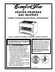
® VENTED PROPANE GAS HEATERS OWNER’S OPERATION AND INSTALLATION MANUAL Models: CGR65BPA, CGR65PA, CGR50BPA, CGR50PA, CGR35PA WARNING: If the information in this manual is not followed exactly, a fire or explosion may result causing property damage, personal injury, or loss of life. FOR YOUR SAFETY — Do not store or use gasoline or other flammable vapors and liquids in the vicinity of this or any other appliance. — WHAT TO DO IF YOU SMELL GAS • Do not try to light any appliance.
CONTENTS SECTION PAGE Safety Information ......................................................................... 3 Product Identification .................................................................... 5 Local Codes ................................................................................... 6 Unpacking .................................................................................... 6 Product Features ............................................................................
SAFETY INFORMATION WARNING ICON G 001 WARNINGS IMPORTANT: Read this owner’s manual carefully and completely before trying to assemble, operate, or service this heater. Improper use of this heater can cause serious injury or death from burns, fire, explosion, electrical shock, and carbon monoxide poisoning. WARNING ICON G 001 DANGER Carbon monoxide poisoning may lead to death! Carbon Monoxide Poisoning: Early signs of carbon monoxide poisoning resemble the flu, with headaches, dizziness, or nausea.
SAFETY INFORMATION Continued WARNING ICON G 001 WARNINGS Continued 7. Provide the following minimum heater clearances from combustibles (as viewed from the front of heater): Front: 48 inches Back: 6 inches Top: 53 inches Right Side: 12 inches Left Side: 6 inches 8. Do not run heater • where flammable liquids or vapors are used or stored • under dusty conditions 9. Never place clothing or any flammable objects on the heater or venting system. 10.
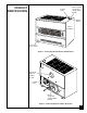
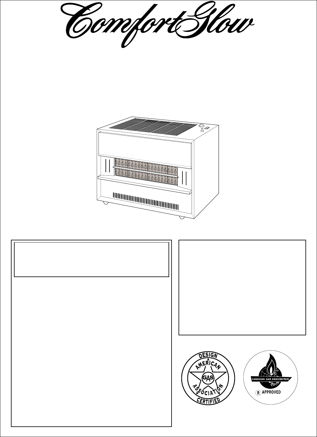
PRODUCT IDENTIFICATION Blower Switch (on models equipped with blower) Control Knob Ignitor Button Burner Radiants Lower Front Access Panel Figure 1 - Vented Propane Gas Heater, Radiant Front Draft Hood Outlet for Venting System Control Valve Blower (on models equipped with blower) Figure 2 - Vented Propane Gas Heater, Rear View 5 100793
LOCAL CODES Install and use heater with care. Follow all local codes. In the absence of local codes, use the latest edition of the following: • National Fuel Gas Code ANSI Z223.1, also known as NFPA 54 * • National Electrical Code ANSI/NFPA 70 * *Available from: American National Standards Institute, Inc., 1430 Broadway, New York, NY 10018; National Fire Protection Association, Inc., Batterymarch Park, Quincy, MA 02269. UNPACKING PRODUCT FEATURES 1. Remove heater from carton. 2.
INSTALLING HEATER Continued LOCATING HEATER WARNING ICON G 001 WARNING Maintain the minimum clearances shown in Figure 3, below. If you can, provide greater clearances. WARNING ICON G 001 WARNING Never install the heater • in a mobile home or a recreational vehicle. • where curtains, furniture, clothing, or other flammable objects are less than 48 inches from the front, 53 inches from the top, 12 inches from the right side and 6 inches from the left side and back of heater.
INSTALLING HEATER VENTING HEATER Note: Venting/chimney materials are not supplied with heater. Continued WARNING ICON G 001 WARNING A qualified service person must install the venting system for this heater. If venting system is not properly installed and maintained, the vent safety shut-off system will prevent the heater from running. Follow all local codes. WARNING ICON G 001 WARNING This heater has a vent safety shut-off system.
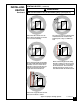
INSTALLING HEATER Continued VENTING HEATER (continued) WARNING ICON G 001 WARNING Do not vent heater in any of the following ways (see Figure 4). ;; ; Heater must be vented to the outdoors. Never vent heater to another room or inside a building. The vertical section of vent pipe must extend at least two feet above the highest point of any roof within ten feet. Never extend vent pipe horizontally through outside wall and terminate. You must connect a vertical run of vent pipe to the horizontal run.
INSTALLING HEATER Continued VENTING HEATER (continued) Proper Size Vent To safely vent heater, the vent connector pipe must be the same diameter as the draft hood outlet on the rear of the heater. Pipe that is too small can cause flue gas to spill from the heater. Fasten vent connector to the draft hood outlet with a sheet metal screw. Vent Types Prefabricated or Masonry All-Fuel Chimney - This is a masonry chimney or a residential-type prefabricated chimney.
INSTALLING HEATER CONNECTING TO GAS SUPPLY WARNING ICON Continued G 001 WARNING A qualified service person must connect heater to gas supply. Follow all local codes. WARNING ICON G 001 CAUTION Never connect heater directly to the propane supply. This heater requires an external regulator (not supplied). Install the external regulator between the heater and propane supply. The installer must supply an external regulator. The external regulator will reduce incoming gas pressure.
INSTALLING HEATER Installation must include a manual shutoff valve, ground joint union, plugged 1/8" NPT tap and a sediment trap. Locate NPT tap within reach for test gauge hook up. NPT tap must be upstream from heater (see Figure 7). Continued Apply pipe joint sealant lightly to male threads. This will prevent excess sealant from going into pipe. Excess sealant in pipe could result in clogged heater valves.
INSTALLING HEATER CHECKING GAS CONNECTIONS WARNING ICON G 001 WARNING Test all gas piping and connections for leaks after installing or servicing. Correct all leaks at once. Continued WARNING ICON G 001 WARNING Never use an open flame to check for a leak. Apply a mixture of liquid soap and water to all joints. Bubbles forming show a leak. Correct all leaks at once. WARNING ICON G 001 CAUTION Make sure external regulator has been installed between propane supply and heater.
INSTALLING HEATER Continued INSTALLING RADIANTS WARNING ICON G 001 WARNING Carefully handle the glass panel. Glass edges are rounded and buffed to prevent cuts, however, chipped or broken sections of glass can present sharp edges. These sharp edges can cut skin. 1. Remove glass guard from across opening at front of heater (see Figure 9). 2. Place radiants into combustion chamber through opening at front of heater. Front of radiant sits on front radiant support (see Figure 10).
INSTALLING HEATER INSTALLING GLASS PANEL For Radiant Models Only 1. Locate the glass panel package inside the back of the heater. Continued WARNING ICON G 001 CAUTION Before installing glass panels, inspect the edges. If you notice any chips or cracks, do not install. If the surface on either side is deeply scratched, do not install. If these conditions exist, call DESA International’s Technical Service Department at 1-800-323-5190 for replacement glass panels.
INSTALLING HEATER 6. Insert top edge of glass panel into the upper glass retaining channel (see Figure 12). WARNING ICON Continued G 001 CAUTION Make sure you insert top edge of glass panels into the upper glass retaining channel. Do not install glass panels with top edge of glass in front of the upper glass retaining channel. Glass panels will not automatically go into the channel. You must guide the glass panels into it. Incorrect installation will damage front of heater due to excess temperatures.
AIR FOR COMBUSTION AND VENTILATION WARNING ICON WARNING G 001 This heater must have fresh air for proper operation. If not, poor fuel combustion and improper venting of flue gases will result. Carbon monoxide poisoning from backed-up flue gases could occur. Read the following instructions to insure proper fresh air for this and other fuel-burning appliances in your home. Today’s homes are built more energy efficient than ever.
AIR FOR COMBUSTION AND VENTILATION Continued In the absence of local codes, use the following excerpts from the National Fuel Gas Code NFPA 54/ANSI Z223.1, Air for Combustion and Ventilation. DETERMINING FRESH-AIR FLOW FOR HEATER LOCATION Example 1: Locating Heater in Unconfined (Open) Area NOTICE An unconfined area has a minimum air volume of 50 cubic feet for each 1000 BTU/Hr input rating of all appliances in the area (cubic feet equals length x width x height of area).
AIR FOR COMBUSTION AND VENTILATION Continued Draft Hood Spillage: This is a hazardous situation. Draft hood spillage releases poisonous carbon monoxide gas into your home. WARNING ICON G 001 DANGER Carbon monoxide poisoning may lead to death! If draft hood spillage occurs, check for blocked flue connectors, vent pipes, and chimneys. If you find blockage, remove. Test again for spillage. If spillage still occurs or there was no blockage, you need more fresh, outside air in the house.
AIR FOR COMBUSTION AND VENTILATION Continued Example 2: Locating Heater in Confined (Closed) Area NOTICE A confined area has an air volume of less than 50 cubic feet for each 1000 BTU/Hr input rating of all appliances in the area (cubic feet equals length x width x height of area). Include adjoining rooms only if there are no doors between the rooms. If you install this heater in a confined area, you must provide additional fresh air.
OPERATING HEATER WARNING ICON G 001 WARNING Heater and venting system surfaces are very hot during operation. Keep children and adults away from hot surfaces to avoid burns and clothing ignition. Carefully supervise young children when they are in the same room as heater. Heater will remain hot for a time after shut down. Let surface cool before touching. NOTICE If operating heater for the first time, a slight odor will occur. This odor will go away after a few hours of operation.
OPERATING HEATER Continued 5. Wait five (5) minutes to clear out any gas. Then smell for gas, including near the floor. If you smell gas, STOP! Follow “B” in the safety information at the top of page 21. If you don’t smell gas, go to the next step. 6. Remove lower front access panel on heater. 7. Turn control knob clockwise Clockwise to the PILOT position. Fully depress control knob for five seconds. Note: You may be running this heater for the first time after hooking up to gas supply.
OPERATING HEATER Continued MANUAL LIGHTING PROCEDURE 1. Remove lower front access panel on heater. 2. Locate pilot. Pilot is attached to the front of burner. 3. Follow steps 1 through 7 under Lighting Instructions, pages 21 and 22. 4. With control knob depressed, strike match. Hold match to pilot until pilot lights. 5. Follow steps 9 through 13 under Lighting Instructions, page 22.
INSPECTING PILOT AND BURNER FLAME Check pilot flame pattern and burner flame pattern often. PILOT FLAME PATTERN Figure 19 shows a correct pilot flame pattern. Figure 20 shows an incorrect pilot flame pattern. The incorrect pilot flame is not touching the thermocouple. This will prevent the thermocouple from getting hot, causing the heater to shut down.
INSPECTING PILOT AND BURNER FLAME Sharp Blue Flame Figure 21 - Correct Burner Flame Pattern Continued Ragged Yellow Flame Flame Lifting Off of Burner Figure 22 - Incorrect Burner Flame Patterns If burner flame pattern is incorrect, as shown in Figure 22 • turn heater off (see To Turn Off Gas to Appliance, page 23) • see Troubleshooting, pages 27 through 31.
CLEANING AND MAINTENANCE WARNING ICON G 001 WARNING Turn off heater and let cool before cleaning or servicing. WARNING ICON WARNING G 001 Keep heater clear and free from combustible materials, gasoline, and other flammable vapors and liquids. WARNING ICON G 001 CAUTION You must keep control areas, burner, and circulating air passageways of heater clean. Inspect these areas of heater before each use. Have heater and venting system inspected yearly by a qualified service person.
TROUBLESHOOTING Note: All troubleshooting items are listed in order of operation. WARNING ICON WARNING G 001 Turn off and unplug heater and let cool before servicing. Unless you need gas supply for testing, shut off manual shutoff valve before servicing. Only a qualified service person should service and repair heater and venting system. WARNING ICON G 001 CAUTION Never use a wire, needle, or similar object to clean pilot. This can damage pilot.
TROUBLESHOOTING Continued OBSERVED PROBLEM POSSIBLE CAUSE Pilot lights but flame goes out when control knob is released. 1. Manual shutoff valve not fully open. 2. Control knob not fully pressed in. 3. Control knob not pressed in long enough. 4. Safety interlock system has been triggered. 5. Thermocouple connection loose at control valve. 6. Pilot flame not touching thermocouple, which allows thermocouple to cool, causing pilot flame to go out.
TROUBLESHOOTING Continued OBSERVED PROBLEM POSSIBLE CAUSE Delayed ignition of burner. 1. Manifold pressure is too low. 2. Burner orifice is clogged. 1. Contact local propane gas company. 2. Clean burner (see Cleaning and Maintenance, page 26) or replace burner orifice (see Changing Burner Orifice, page 34). Burner backfiring during combustion. 1. Burner orifice is clogged or damaged. 1.
TROUBLESHOOTING Continued OBSERVED PROBLEM POSSIBLE CAUSE Burner fails to respond to thermostat. 1. Pilot flame not lit. 2. Pilot flame not properly heating end of thermocouple. 3. Pilot burner orifice clogged or damaged. 4. Control valve defective. 5. Temperature at thermostat bulb satisfied. Heater produces a whistling noise when burner is lit. 1. Air in gas line. 2. Air passageways on heater blocked. 3. Dirty or partially clogged burner orifice.
TROUBLESHOOTING WARNING ICON G 001 WARNING If you smell gas • Shut off gas supply. • Do not try to light any appliance. • Do not touch any electrical switch; do not use any phone in your building. • Immediately call your gas supplier from a neighbor’s phone. Follow the gas supplier’s instructions. • If you cannot reach your gas supplier, call the fire department. OBSERVED PROBLEM POSSIBLE CAUSE Heater produces unwanted odors. 1. Heater burning vapors from paint, hair spray, glues, etc. 2.
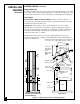
SERVICE PROCEDURES Removing Control Valve and Burner Tube 1. Shut off gas supply to heater. 2. Remove lower front access panel on heater. 3. Disconnect burner tube from orifice holder (see Figure 23). 4. Remove pilot gas line from control valve (see Figure 23). 5. Disconnect wire connectors from thermocouple interrupter (see Figure 23). 6. Remove thermocouple and thermocouple interrupter from control valve. 7. Remove cotter pin from control valve. This releases the control rod from valve (see Figure 23). 8.
SERVICE PROCEDURES Continued Removing Burner 1. Shut off gas supply to heater. 2. Remove lower front access panel on heater. 3. Disconnect burner tube from orifice holder (see Figure 24). 4. Remove orifice holder from burner (see Figure 24). 5. Remove pilot burner bracket nuts and remove pilot assembly (see Figure 24). 6. Move burner to the right for clearance. Rotate burner 90° and remove burner through lower front access opening. 7. To reinstall, reverse above steps.
SERVICE PROCEDURES Continued Burner Changing Burner Orifice 1. Shut off gas supply to heater. 2. Remove lower front access panel on heater. 3. Disconnect burner tube from orifice holder (see Figure 25). 4. Remove orifice holder from burner (see Figure 25). 5. Use socket or open-end wrench to remove the old orifice from the orifice holder. 6. Clean and replace orifice, or replace with new orifice. 7. Turn on gas to heater and check for gas leaks. Apply a mixture of liquid soap and water to all joints.
TECHNICAL SERVICE SPECIFICATIONS You may have further questions about installation, operation, or troubleshooting. If so, contact DESA International’s Technical Service Department at 1-800-3235190. 35,000 BTU/Hr Model BTU 35,000 Type Gas Propane Only Ignition Piezo Pressure Regulator Setting 10.5" W.C. Inlet Gas Pressure Maximum 14" W.C. Minimum 11" W.C. Dimensions, Inches Heater (H x W x D) 25 x 27 1/4 x 16 Shipping Weight (pounds) 97 Flue Vent Size 4" dia. Orifice Size 52 drill, ø .
ORDERING REPLACEMENT PARTS Note: Use only original replacement parts. This will protect your warranty cover- age for parts replaced under warranty. Parts Under Warranty Contact your nearest dealer or call DESA International’s Technical Service Department at 1-800-323-5190.
ACCESSORIES Purchase these heater accessories from your local dealer. If they can not supply these accessories, contact your nearest Parts Central (see page 36). You can also write to the address listed on the back page of this manual for information. BLOWER KIT - PART NUMBER GA6010 For all models. Provides better heat distribution. Makes heater more efficient. Complete installation and operating instructions provided with blower. MANUAL SHUTOFF VALVE - GA5010 For all models.
ILLUSTRATED PARTS LIST Blower Assembly This list contains replaceable parts used in your heater. When ordering parts, follow the instructions listed under Ordering Replacement Parts on page 36 of this manual. 1 2 9 3 4 8 6 5 7 PART NUMBER FOR KEY NO. CGR65BPA CGR65PA CGR50BPA CGR50PA CGR35PA DESCRIPTION QTY.
ILLUSTRATED PARTS LIST Cabinet Assembly for Radiant Models This list contains replaceable parts used in your heater. When ordering parts, follow the instructions listed under Ordering Replacement Parts on page 36 of this manual. 6 10 8 11 4 7 9 6 3 6 5 2 1 PART NUMBER FOR KEY NO.
ILLUSTRATED PARTS LIST Burner Assembly for Radiant Models 1 3 2 4 50 and 65 Models 11 29 6 7 28 35 Model Only 7 6 27 8 5 22 10 11 23 9 7 26 13 24 30 31 25 12 21 16 14 19 15 20 18 16 4 17 40 100793
PARTS LIST Burner Assembly for Radiant Models This list contains replaceable parts used in your heater. When ordering parts, follow the instructions listed under Ordering Replacement Parts on page 36 of this manual. PART NUMBER FOR KEY NO.
NOTES _________________________________________________________________ _________________________________________________________________ _________________________________________________________________ _________________________________________________________________ _________________________________________________________________ _________________________________________________________________ _________________________________________________________________ ___________________________________________
NOTES _________________________________________________________________ _________________________________________________________________ _________________________________________________________________ _________________________________________________________________ _________________________________________________________________ _________________________________________________________________ _________________________________________________________________ ___________________________________________
WARRANTY INFORMATION Always specify model and serial numbers when communicating with the factory. We reserve the right to amend these specifications at any time without notice. The only warranty applicable is our standard written warranty. We make no other warranty, expressed or implied.