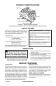
F PI LO LO OF HI REMOTE OFF N TO UNVENTED (VENT-FREE) GAS LOG HEATER OWNER’S OPERATION AND INSTALLATION MANUAL Patent Pending 18", 24" and 30" Variable Manually-Controlled Models CRL2718PA/NA CRL3124PA/NA 18", 24" and 30" Thermostatically-Controlled Models CCL3018PTA/NTA CCL3924PTA/NTA Biltmore Split Oak, Seasonal Oak and Smoky Mountain Oak Logs Variable Manually-Controlled Models Also Design-Certified As Vented Decorative Appliances WARNING: If the information in this manual is not followed exac
Table of Contents Safety................................................................... 2 Product Identification............................................ 5 Local Codes......................................................... 5 Unpacking............................................................ 5 Product Features.................................................. 5 Air for Combustion and Ventilation....................... 6 Installation............................................................
SAFETY Continued WARNING: This product contains and/or generates chemicals known to the state of California to cause cancer or birth defects or other reproductive harm. IMPORTANT: Read this owner’s manual carefully and completely before trying to assemble, operate or service this heater. Improper use of this heater can cause serious injury or death from burns, fire, explosion, electrical shock and carbon monoxide poisoning.
SAFETY Continued 1. This appliance is only for use with the type of gas indicated on the rating plate. This appliance is not convertible for use with other gases. 2. Do not place propane/LP supply tank(s) inside any structure. Locate propane/LP supply tank(s) outdoors (propane/LP units only). 3. To prevent performance problems, do not use propane/LP fuel tank of less than 100 lb. capacity (propane/LP units only). 4.
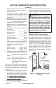
Product Identification Log Set Burner Piezo Ignitor Control Knob Base Grate Figure 1 - Vent-Free Gas Log Heater (Logs May Vary by Model, Seasonal Oak Single Burner Model Shown) Local Codes Install and use heater with care. Follow all local codes. In the absence of local codes, use the latest edition of The National Fuel Gas Code, ANSI Z223.1/NFPA 54*. *Available from: American National Standards Institute, Inc. 1430 Broadway New York, NY 10018 National Fire Protection Association, Inc.
Air for Combustion and Ventilation WARNING: This heater shall not be installed in a room or space unless the required volume of indoor combustion air is provided by the method described in the National Fuel Gas Code, ANSI Z223.1/NFPA 54, the International Fuel Gas Code, or applicable local codes. Read the following instructions to insure proper fresh air for this and other fuel-burning appliances in your home. Today’s homes are built more energy efficient than ever.
AIR FOR COMBUSTION AND VENTILATION Continued Example: Space size 20 ft. (length) x 16 ft. (width) x 8 ft. (ceiling height) = 2,560 cu. ft. (volume of space) If additional ventilation to adjoining room is supplied with grills or openings, add the volume of these rooms to the total volume of the space. 2. Multiply the space volume by 20 to determine the maximum Btu/Hr the space can support. _ ________ (volume of space) x 20 = (Maximum Btu/Hr the space can support) Example: 2,560 cu. ft.
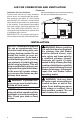
AIR FOR COMBUSTION AND VENTILATION Continued Ventilation Air From Outdoors Provide extra fresh air by using ventilation grills or ducts. You must provide two permanent openings: one within 12" of the ceiling and one within 12" of the floor. Connect these items directly to the outdoors or spaces open to the outdoors. These spaces include attics and crawl spaces. Follow the National Fuel Gas Code, ANSI Z223.1/NFPA 54, SAir for Combustion and Ventilation for required size of ventilation grills or ducts.
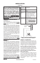
INSTALLATION Continued WARNING: Never install the heater • in a bedroom or bathroom unless installed as a vented appliance (Variable ManuallyControlled Models Only) (see page 12) • in a recreational vehicle • where curtains, furniture, clothing or other flammable objects are less than 42" from front, top or sides of heater • in high traffic areas • in windy or drafty areas CAUTION: This heater creates warm air currents. These currents move heat to wall surfaces next to heater.
INSTALLATION Continued NOTICE: Manual control heaters may be used as a vented product. If so, you must always run heater with chimney flue damper open. If running heater with damper open, noncombustible material above fireplace opening is not needed. Go to Installing Damper Clamp Accessory for Vented Operation, page 12. Minimum Noncombustible Material Clearances If Not Using Mantel Note: If using a mantel, proceed to If Using Mantel. If not using a mantel, follow the information below.
INSTALLATION Continued NOTICE: Surface temperatures of adjacent walls and mantels become hot during operation. Walls and mantels above the firebox may become hot to the touch. If installed properly, these temperatures meet the requirement of the national product standard. Follow all minimum clearances shown in this manual.
INSTALLATION Continued INSTALLING DAMPER CLAMP ACCESSORY FOR VENTED OPERATION Note: When used as a vented heater, appliance must be installed only in a solid-fuel burning fireplace with a working flue and constructed of noncombustible material. For Massachusetts Residents Only: Installation of this gas log set as a vented appliance in the Commonwealth of Massachusetts requires the damper be permanently removed or welded in the fully open position.
INSTALLATION Continued IMPORTANT: Make sure the heater burners are level. If heater is not level, heater will not work properly. For thermostat models, avoid damage to thermostat bulb. Avoid nicks or sharp bends in thermostat bulb wire. Keep thermostat bulb in mounting bracket until ready to mount base to floor. See Optional Positioning Of Thermostat Sensing Bulb, page 29.
INSTALLATION Continued CAUTION: Never connect heater directly to the propane/LP supply. This heater requires an external regulator (not supplied). Install the external regulator between the heater and propane/ LP supply. CAUTION: Use only new, black iron or steel pipe. Internally-tinned copper tubing may be used in certain areas. Check your local codes. Use pipe of 1/2" diameter or greater to allow proper gas volume to heater. If pipe is too small, undue loss of volume will occur.
INSTALLATION Continued CAUTION: Avoid damage to regulator. Hold gas regulator with wrench when connecting it to gas piping and/or fittings. Propane/LP From External Regulator (11" W.C.** to 14" W.C. Pressure) Natural From Gas Meter (5" W.C.** to 10.5" W.C.
INSTALLATION INSTALLING LOGS Continued 2. Open main gas valve located on or near gas meter for natural gas or open propane/LP supply tank valve. 3. Make sure control knob of heater is in the OFF position. 4. Check all joints from equipment shutoff valve to thermostat gas valve (Thermostat-Controlled Models) or to control valve (Manually-Controlled Models) (see Figures 17 and 18). Apply noncorrosive leak detection fluid to all joints. Bubbles forming show a leak. 5. Correct all leaks at once. 6.
INSTALLATION Continued 3. Locate pins on bottom of back log (#3). Slide these pins into holes in grate base behind burner (see Figure 21). 4. Locate holes on bottom of crossover log (#4). Slide front hole onto left pin (CCL3924PTA/ NTA) or middle pin (CCL3018PTA/NTA) on middle log (#2) and pin on back log (#3). See Figure 22, for placement. 5. For CCL3924PTA/NTA Only: Locate pin and hole on bottom of crossover log (#5). Slide pin into hole located in crossover log (#4).
INSTALLATION Back Log Continued Crossover Log (#6) Post Base Assembly 6 Pins Front Log (#1) Middle Log (#2) Post Figure 26 - Installing Back Log Figure 25 - Installing Crossover Log #6 (CCL3924PTA/NTA Shown) Front Log Single Burner Seasonal Oak Models CRL2718PA/NA, CRL3124PA/NA WARNING: Failure to position the parts in accordance with these diagrams or failure to use only parts specifically approved with this heater may result in property damage or personal injury.
Operation Manually-Controlled Models LIGHTING INSTRUCTIONS FOR YOUR SAFETY READ BEFORE LIGHTING WARNING: If you do not follow these instructions exactly, a fire or explosion may result causing property damage, personal injury or loss of life. A. This appliance has a pilot which must be lighted by hand. When lighting the pilot, follow these instructions exactly. B. BEFORE LIGHTING smell all around the appliance area for gas.
Operation Continued Manually-Controlled Models 5. Slightly press and turn control knob counterclockwise to the PILOT position. Press in control knob for five (5) seconds (see Figure 29). Note: You may be running this heater for the first time after hooking up to gas supply. If so, the control knob may need to be pressed in for 30 seconds or more. This will allow air to bleed from the gas system. 6. With control knob pressed in, press and release ignitor button. This will light pilot.
Operation Continued Thermostat-Controlled Models LIGHTING FOR YOUR SAFETY INSTRUCTIONS READ BEFORE LIGHTING WARNING: If you do not follow these instructions exactly, a fire or explosion may result causing property damage, personal injury or loss of life. A. This appliance has a pilot which must be lighted by hand. When lighting the pilot, follow these instructions exactly. B. BEFORE LIGHTING smell all around the appliance area for gas.
Operation Continued Thermostat-Controlled Models 5. Turn control knob counterclockwise to the PILOT position. Press in control knob for five (5) seconds (see Figure 31). Note: You may be running this heater for the first time after hooking up to gas supply. If so, the control knob may need to be pressed in for 30 seconds or more. This will allow air to bleed from the gas system. • If control knob does not pop out when released, contact a qualified service person or gas supplier for repairs. 6.
Inspecting Burners Check pilot flame pattern and burner flame patterns often. PILOT FLAME PATTERN Figure 33 shows a correct pilot flame pattern. Figure 34 shows an incorrect pilot flame pattern. The incorrect pilot flame is not touching the thermocouple. This will cause the thermocouple to cool. When the thermocouple cools, the heater will shut down.
CLEANING AND MAINTENANCE Continued 1. Shut off unit, including pilot. Allow unit to cool for at least thirty minutes. 2. Inspect burner, pilot and primary air inlet holes on injector holder for dust and dirt (see Figure 35). 3. Blow air through the ports/slots and holes in the burner. 4. Check the injector holder located at the end of the burner tube again. Remove any large particles of dust, dirt, lint or pet hair with a soft cloth or vacuum cleaner nozzle. 5.
Troubleshooting WARNING: Turn off heater and let cool before servicing. Only a qualified service person should service and repair heater. CAUTION: Never use a wire, needle or similar object to clean ODS/pilot. This can damage ODS/pilot unit. Note: All troubleshooting items are listed in order of operation. OBSERVED PROBLEM POSSIBLE CAUSE REMEDY When ignitor button is pressed, there is no spark at ODS/pilot 1. Ignitor electrode not connected to ignitor cable 2. Ignitor cable pinched or wet 1.
TROUBLESHOOTING Continued OBSERVED PROBLEM POSSIBLE CAUSE REMEDY ODS/pilot lights but flame goes out when control knob is released 1. Control knob not fully pressed in 2. Control knob not pressed in long enough 1. Press in control knob fully 3. Equipment shutoff valve not fully open 4. Pilot flame not touching thermocouple, which allows thermocouple to cool, causing pilot flame to go out.
TROUBLESHOOTING Continued OBSERVED PROBLEM POSSIBLE CAUSE REMEDY Moisture/condensation noticed on windows 1. Not enough combustion/ ventilation air 1. Refer to Air for Combustion and Ventilation requirements (page 6) Heater produces a whistling noise when burner is lit 1. Turning control knob to HI or position 5 when burner is cold 2. Air in gas line 1. Turn control knob to LO or position 1 and let warm up for a minute 2. Operate burner until air is removed from line.
TROUBLESHOOTING Continued WARNING: If you smell gas • Shut off gas supply. • Do not try to light any appliance. • Do not touch any electrical switch; do not use any phone in your building. • Immediately call your gas supplier from a neighbor’s phone. Follow the gas supplier’s instructions. • If you cannot reach your gas supplier, call the fire department. IMPORTANT: Operating heater where impurities in air exist may create odors.
Optional Positioning of Thermostat Sensing Bulb For Masonry and Factorybuilt Metal Fireplace If your log set cycles to pilot, but the room temperature drops to a lower than ideal comfort level before the log set comes back on, you may want to reposition the thermostat sensing bulb. The thermostat sensing bulb is located near the gas valve assembly on the mounting bracket. This location allows the thermostat to keep the room temperature at an ideal comfort level for most fireplace applications.
OPTIONAL POSITIONING OF THERMOSTAT SENSING BULB Continued thoroughly. Remove the paper backing from the adhesive on back of mounting clip. Press the clip into the new location so that the thermostat sensing bulb will be positioned vertically with the capillary at the bottom (see Figure 43). Slide the thermostat sensing bulb into the clip. IMPORTANT: Do not crimp capillary.
Accessories Purchase these accessories from your local dealer. If they can not supply these accessories, either contact your nearest Parts Central or call DESA Heating, LLC at 1-866-672-6040 for information. You can also write to the address listed on the back page of this manual. DAMPER CLAMP - GA6080 Permanently opens chimney flue damper for vented operation. Can be used only with non-thermostat accessories.
PARTS Thermostatically-Controlled Biltmore Split Oak Models CCL3018PTA, ccl3018nta, CCL3924PTA and CCL3924NTA Peg positions vary according to model. 2 5 1 4 22 20 14 24 21 13 7 12 15 6 7 25 11 16 10 8 23 17 23 23 18 9 21 19 23 32 www.desatech.
PARTS Thermostatically-Controlled Biltmore Split Oak Models KEY NO. PART NO.
PARTS Variable Manually-Controlled Seasonal Oak Models CRL2718PA, CRL2718NA, CRL3124PA AND CRL3124NA 3B 3A 1 2 20 18 17 19 10 11 12 7 5 8 9 6 6 4 13 21 18 6 19 16 15 34 14 www.desatech.
PARTS Variable Manually-Controlled Seasonal Oak Models This list contains replaceable parts used in your heater. When ordering parts, follow the instructions listed under Replacement Parts, below. PART NUMBER KEY NO.
Warranty KEEP THIS WARRANTY Model (located on product or identification tag)______________________________ Serial No. (located on product or identification tag)___________________________ Date Purchased ___________________________ Keep receipt for warranty verification.