VENT-FREE FREESTANDING PEDESTAL STOVE SYSTEM OWNER’S OPERATION AND INSTALLATION MANUAL THERMOSTATICALLY - CONTROLLED MODELS S26PTA AND S26NTA 20,000 TO 26,000 BTU/HR WARNING: If the information in this manual is not followed exactly, a fire or explosion may result causing property damage, personal injury, or loss of life. — Do not store or use gasoline or other flammable vapors and liquids in the vicinity of this or any other appliance. — WHAT TO DO IF YOU SMELL GAS • Do not try to light any appliance.
WARNING: Improper installation, adjustment, alteration, service, or maintenance can cause injury or property damage. Refer to this manual for correct installation and operational procedures. For assistance or additional information consult a qualified installer, service agency, or the gas supplier. WARNING: This is an unvented gas-fired heater. It uses air (oxygen) from the room in which it is installed. Provisions for adequate combustion and ventilation air must be provided.
SAFETY INFORMATION WARNING: This product contains and/or generates chemicals known to the state of California to cause cancer or birth defects, or other reproductive harm. IMPORTANT: Read this owner’s manual carefully and completely before trying to assemble, operate, or service this heater. Improper use of this heater can cause serious injury or death from burns, fire, explosion, electrical shock, and carbon monoxide poisoning.
SAFETY INFORMATION Continued 1. This appliance is only for use with the type of gas indicated on the rating plate. This appliance is not convertible for use with other gases. 2. Do not place propane/LP supply tank(s) inside any structure. Locate propane/LP supply tank(s) outdoors (propane/LP gas units only). 3.
LOCAL CODES Install and use heater with care. Follow all local codes. In the absence of local codes, use the latest edition of The National Fuel Gas Code, ANSI Z223.1/NFPA 54*. *Available from: American National Standards Institute, Inc. 1430 Broadway New York, NY 10018 National Fire Protection Association, Inc. Batterymarch Park Quincy, MA 02269 UNPACKING 1. 2. 3. 4. 5. 6. Remove top inner pack. Tilt carton so that stove is upright. Remove protective side packaging. Slide stove out of carton.
AIR FOR COMBUSTION AND VENTILATION Continued Unusually tight construction is defined as construction where: a. walls and ceilings exposed to the outside atmosphere have a continuous water vapor retarder with a rating of one perm (6 x 10-11 kg per pa-sec-m2) or less with openings gasketed or sealed and b. weather stripping has been added on openable windows and doors and c.
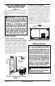
AIR FOR COMBUSTION AND VENTILATION Continued If the actual Btu/Hr used is less than the maximum Btu/Hr the space can support, the space is an unconfined space. You will need no additional fresh air ventilation. WARNING: If the area in which the heater may be operated is smaller than that defined as an unconfined space or if the building is of unusually tight construction, provide adequate combustion and ventilation air by one of the methods described in the National Fuel Gas Code, ANSI Z223.
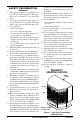
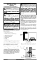
INSTALLATION Continued WARNING: Never install the heater • in a bedroom or bathroom • in a recreational vehicle • where curtains, furniture, clothing, or other flammable objects are less than 42 inches from the front, top, or sides of the heater • in high traffic areas • in windy or drafty areas the floor. IMPORTANT: You must maintain minimum wall and ceiling clearances during installation. The minimum clearances are shown in Figure 4. Measure from outermost point of stove top.
INSTALLATION Continued CONNECTING TO GAS SUPPLY WARNING: A qualified service person must connect heater to gas supply. Follow all local codes. CAUTION: Never connect propane/LP heater directly to the propane/LP supply. This heater requires an external regulator (not supplied). Install the external regulator between the heater and propane/LP supply. WARNING: Never connect natural gas heater to private (nonutility) gas wells. This gas is commonly known as wellhead gas.
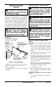
INSTALLATION Continued WARNING: Use pipe joint sealant that is resistant to liquid petroleum (LP) gas. We recommend that you install a sediment trap in supply line as shown in Figure 7. Locate sediment trap where it is within reach for cleaning. Install in piping system between fuel supply and heater. Locate sediment trap where trapped matter is not likely to freeze. A sediment trap traps moisture and contaminants. This keeps them from going into heater controls.
Equipment Shutoff Valve INSTALLATION Continued 2. Pressurize supply piping system by either opening propane/LP supply tank valve for propane/LP gas, opening main gas valve located on or near gas meter for natural gas, or using compressed air. 3. Check all joints from gas meter to equipment shutoff valve (see Figures 9 and 10). Apply noncorrosive leak detection fluid to gas joints. Bubbles forming show a leak. 4. Correct all leaks at once. Pressure Testing Heater Gas Connections 1.
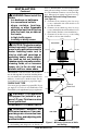
INSTALLATION Continued IMPORTANT: Make sure log does not cover any burner ports (see Figure 12). One Piece Burner Ports Log Set 9. Route ends of 3-wire power cord up from the lower control compartment through the plastic bushing, then up to the upper cavity of stove (see Figure 17, page 13). 10. Attach the terminal ends of the white and black power cord wires to the terminals on the blower motor (see Figure 14). Push firmly. 11.
INSTALLATION Blower Bracket Blower WARNING: Electrical Grounding Instructions: This appliance is equipped with a threeprong (grounding) plug for your protection against shock hazard and should be plugged directly into a properly grounded threeprong receptacle. 19. Using speed control knob, turn blower on and check for operation. 20. All remaining parts from blower kit may be discarded.
OPERATING HEATER FOR YOUR SAFETY READ BEFORE LIGHTING WARNING: If you do not follow these instructions exactly, a fire or explosion may result causing property damage, personal injury or loss of life. A. This appliance has a pilot which must be lighted by hand. When lighting the pilot, follow these instructions exactly. B. BEFORE LIGHTING smell all around the appliance area for gas. Be sure to smell next to the floor because some gas is heavier than air and will settle on the floor.
OPERATING HEATER Continued Ignitor Electrode Thermocouple Pilot Burner Figure 20 - Pilot rect pilot flame is not touching the thermocouple. This will cause the thermocouple to cool. When the thermocouple cools, the heater will shut down.
CLEANING AND MAINTENANCE WARNING: Turn off heater and let cool before cleaning. CAUTION: You must keep control areas, burner, and circulating air passageways of heater clean. Inspect these areas of heater before each use. Have heater inspected yearly by a qualified service person. Heater may need more frequent cleaning due to excessive lint from carpeting, bedding material, pet hair, etc. WARNING: Failure to keep the primary air opening(s) of the burner(s) clean may result in sooting and property damage.
CLEANING AND MAINTENANCE Continued CABINET Air Passageways • Use a vacuum cleaner or pressurized air to clean. Exterior • Use a soft cloth dampened with a mild soap and water mixture. Wipe the cabinet to remove dust. LOGS • If you remove logs for cleaning, refer to Installing Logs, pages 11 and 12, to properly replace logs. • Replace log(s) if broken or chipped (dime-sized or larger).
TROUBLESHOOTING Note: All troubleshooting items are listed in order of operation. WARNING: Turn off heater and let cool before servicing. Only a qualified service person should service and repair heater. CAUTION: Never use a wire, needle, or similar object to clean ODS/pilot. This can damage ODS/pilot unit. OBSERVED PROBLEM POSSIBLE CAUSE REMEDY When ignitor button is pressed, there is no spark at ODS/pilot 1. Ignitor electrode not connected to ignitor cable 2. Ignitor cable pinched or wet 1.
TROUBLESHOOTING OBSERVED PROBLEM ODS/pilot lights but flame goes out when control knob is released Burner does not light after ODS/ pilot is lit Continued POSSIBLE CAUSE REMEDY 1. Control knob not fully pressed in 2. Control knob not pressed in long enough 3. Equipment shutoff valve not fully open 4. Pilot flame not touching thermocouple, which allows thermocouple to cool, causing pilot flame to go out.
TROUBLESHOOTING OBSERVED PROBLEM Continued POSSIBLE CAUSE Heater produces a whistling noise when burner is lit 1. Turning control knob to HI position when burner is cold 2. Air in gas line 3. Air passageways on heater blocked 4. Dirty or partially clogged burner orifice Dark residue on logs or inside of fireplace 1. Improper log placement 2. Drafts or other air currents affecting flame pattern 3. Air holes at burner inlet blocked 4. Burner flame holes blocked REMEDY 1.
TROUBLESHOOTING Continued WARNING: If you smell gas Shut off gas supply. Do not try to light any appliance. Do not touch any electrical switch; do not use any phone in your building. Immediately call your gas supplier from a neighbor’s phone. Follow the gas supplier’s instructions. • If you cannot reach your gas supplier, call the fire department. • • • • IMPORTANT: Operating heater where impurities in air exist may create odors.
ILLUSTRATED PARTS BREAKDOWN MODELS S26PTA AND S26NTA (Shown) 1 2 9 5 3 6 4 14 8 12 9 7 10 11 13 22 www.desatech.
PARTS LIST This list contains replaceable parts used in your heater. When ordering parts, follow the instructions listed under Replacement Parts on page 26 of this manual. KEY NO.
ILLUSTRATED PARTS BREAKDOWN MODELS S26PTA AND S26NTA 13 5 1 10 18 6 11 8 4 9 17 12 2 16 3 15 7 14 14 24 www.desatech.
PARTS LIST MODELS S26PTA AND S26NTA This list contains replaceable parts used in your heater. When ordering parts, follow the instructions listed under Replacement Parts on page 26 of this manual. KEY NO. PART NO.
REPLACEMENT PARTS ACCESSORIES Note: Use only original replacement parts. This will protect your warranty coverage for parts replaced under warranty. Purchase these heater accessories from your local dealer or Parts Central (see page 27). If they cannot supply these accessories call DESA Heating Products’ Sales Department at 1-866-672-6040 for referral information. You can also write to the address listed on the back page of this manual. PARTS UNDER WARRANTY Contact authorized dealers of this product.
PARTS CENTRAL These Parts Centrals are privately owned businesses. They have agreed to support our customer’s needs by providing original replacement parts and accessories. Baltimore Electric 1348 Dixwell Avenue Hamden, CT 06514-0322 1-800-397-7553 203-248-7553 Parts Department Portable Heater Parts 342 N. County Rd. 400 East Valparaiso, IN 46383-9704 All States 219-462-7441 1-888-619-7060 sales@portableheaterparts.com techservice@portableheaterparts.
WARRANTY INFORMATION KEEP THIS WARRANTY Model Serial No. Date Purchased Always specify model and serial numbers when communicating with the factory. We reserve the right to amend these specifications at any time without notice. The only warranty applicable is our standard written warranty. We make no other warranty, expressed or implied.