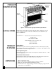
VENT-FREE PROPANE/LP GAS HEATER OWNER’S OPERATION AND INSTALLATION MANUAL ® Shown with Optional Hearth Base and Mantel 14,000 to 28,000 Btu/Hr with Thermostat “B” Models WARNING: If the information in this manual is not followed exactly, a fire or explosion may result causing property damage, personal injury, or loss of life. — Do not store or use gasoline or other flammable vapors and liquids in the vicinity of this or any other appliance.
CONTENTS SECTION PAGE Safety Information ................................................................................... 2 Product Identification .............................................................................. 4 Local Codes ............................................................................................. 4 Product Features ...................................................................................... 4 Unpacking ......................................................
SAFETY INFORMATION Continued . WARNING ICON G 001 WARNINGS Continued WARNING: Any change to this heater or its controls can be dangerous. 1. This appliance is only for use with the type of gas indicated on the rating plate. This appliance is not convertible for use with other gases. 2. Do not place propane/LP supply tank(s) inside any structure. Locate propane/ LP supply tank(s) outdoors. 3.
Ignitor Button d'f fgp irln fgpd'f d'f dk go dkirln fgp d'f irln mk oe mkgo dk irlnfgp d'f fgp go idk kd idkoe mk go dk irln fgpd'f I als kd idkoe mk go dk irln fgpd'f FJ als d'f dk oe GL FJI alskd idk oemk go dkirln fgp d'f KI I kd idk irln fgp mk DF GL FJ als d'f oe mkgo dk AS DFKI GL FJI alskd idk go dkirln fgp d'f oe d'f KI I kd fgp d'fAS DF KIGL FJ I als kdidk oemk go dkirln fgp d'f irln AS irln mk GL dk irlnfgp d'f ASDF KI GLFJ I als kdidk oe mkgo dk irlnfgp d'f go DF fgp d'f FJ als idk oe go d'f mk
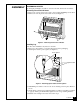
ASSEMBLY ASSEMBLING HEATER Tools Required: Phillips screwdriver, 5/16" hex wrench, and slotted screwdriver Removing Front Panel Of Heater 1. Remove two screws near bottom corners of front panel with Phillips screwdriver. 2. Pull bottom of front panel forward, then down (see Figure 2) . Figure 2 - Removing Front Panel of Heater Installing Log Note: For easier installation, lay heater on its back. 1. Remove log from inside top of heater. Discard protective packaging. 2.
ASSEMBLY WARNING ICON Continued G 001 WARNING Always have burner shield and screen in place before operating heater. This prevents excessive temperatures on heater surfaces. Failure to position the parts in accordance with these diagrams or failure to use only parts specifically approved with this heater may result in property damage or personal injury.
ASSEMBLY Continued Assembling and Attaching Brass Trim 1. Remove packaging from three remaining pieces of brass trim. 2. Locate four brass screws, two adjusting plates with set screws, and two shims in the hardware packet. 3. Align shim under adjusting plate as shown in Figure 6. 4. Slide one end of adjusting plate/shim in slot on mitered edge of top brass trim (see Figure 6). 5. Slide other end of adjusting plate/shim in slot on mitered edge of side brass trim (see Figure 6). 6.
FRESH AIR FOR COMBUSTION AND VENTILATION WARNING ICON G 001 WARNING This heater shall not be installed in a confined space unless provisions are provided for adequate combustion and ventilation air. Read the following instructions to insure proper fresh air for this and other fuel-burning appliances in your home. Today’s homes are built more energy efficient than ever. New materials, increased insulation, and new construction methods help reduce heat loss in homes.
FRESH AIR FOR COMBUSTION AND VENTILATION Continued DETERMINING FRESH-AIR FLOW FOR HEATER LOCATION Determining if You Have a Confined or Unconfined Space Use this worksheet to determine if you have a confined or unconfined space. Space: Includes the room in which you will install heater plus any adjoining rooms with doorless passageways or ventilation grills between the rooms. 1. Determine the volume of the space (length x width x height). Length x Width x Height = ___________________ cu. ft.
FRESH AIR FOR COMBUSTION AND VENTILATION Continued WARNING ICON G 001 WARNING If the area in which the heater may be operated is smaller than that defined as an unconfined space, provide adequate combustion and ventilation air by one of the methods described in the National Fuel Gas Code, ANSI Z223.1, 1992, Section 5.3. VENTILATION AIR Ventilation Air From Inside Building This fresh air would come from an adjoining unconfined space.
FRESH AIR FOR COMBUSTION AND VENTILATION Continued Ventilation Air From Outdoors Provide extra fresh air by using ventilation grills or ducts. You must provide two permanent openings: one within 12" of the ceiling and one within 12" of the floor. Connect these items directly to the outdoors or spaces open to the outdoors. These spaces include attics and crawl spaces. IMPORTANT: Do not provide openings for inlet or outlet air into attic if attic has a thermostat-controlled power vent.
INSTALLATION NOTICE A qualified service person must install heater. Follow all local codes. CHECK GAS TYPE Use only propane/LP gas. If your gas supply is not propane/LP, do not install heater. Call dealer where you bought heater for proper type heater. INSTALLATION ITEMS Before installing heater, make sure you have the items listed below.
INSTALLATION WARNING ICON Continued G 001 CAUTION If you install the heater in a home garage • heater pilot and burner must be at least 18 inches above floor. • locate heater where moving vehicle will not hit it. For convenience and efficiency, install heater • where there is easy access for operation, inspection, and service. • in coldest part of room. An optional fan kit is available from your dealer. See Accessories, page 34. If planning to use fan, locate heater near an electrical outlet.
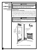
INSTALLATION Continued INSTALLATION OPTIONS There are three options for mounting this heater. A. Mounting heater to wall B. Mounting heater to optional hearth base C. Mounting heater with optional hearth base to optional mantel. A. MOUNTING HEATER TO WALL Mounting Bracket The mounting bracket is located on back panel of heater. It has been taped there for shipping. Remove mounting bracket from back panel.
INSTALLATION Continued Attaching Mounting Bracket to Wall Note: Wall anchors, mounting screws, and spacers are in hardware package. The hardware package is provided with heater. Attaching to wall stud method For attaching mounting bracket to wall studs. 1. Drill holes at marked locations using 9/64" drill bit. 2. Place mounting bracket onto wall. Line up last hole on each end of bracket with holes drilled in wall. 3. Insert mounting screws through bracket and into wall studs. 4.
INSTALLATION Continued Installing Bottom Mounting Screws 1. Locate two bottom mounting holes. These holes are near bottom on back panel of heater (see Figure 17). 2. Mark screw locations on wall. 3. Remove heater from mounting bracket. 4. If installing bottom mounting screws into hollow or solid wall, install wall anchors. Follow steps 1 through 4 under Attaching To Wall Anchor Method, page 15. If installing bottom mounting screw into wall stud, drill holes at marked locations using 9/64" drill bit. 5.
INSTALLATION Continued If securing to a concrete floor, drill a 1 3/8" deep hole using a 1/4" diameter concrete drill bit. Completely insert anchors into each hole. 3. Mount heater to hearth base following steps under Mounting Heater to Optional Hearth Base, page 17. After mounting heater, position heater and hearth base over drilled holes. With slotted screwdriver, secure hearth base to floor with four wood screws. Mounting Heater to Optional Hearth Base 1.
INSTALLATION Continued C. MOUNTING HEATER WITH OPTIONAL HEARTH BASE TO OPTIONAL MANTEL (The following instructions are for GMF800(A,B)/GMU801(A,B) models only. For other mantels, see instructions included with mantel kit.) Assembling Mantel IMPORTANT: Only use the optional mantels specified in this manual. See Accessories, page 34 for proper mantel kits. This heater is only approved for use with models GMF800(A,B)/GMU801(A,B), GM900F(A,B)/GM901U(A,B), and GM700F/GM701U mantel kits.
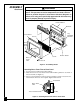
INSTALLATION Continued 2. Locate pre-drilled holes at bottom of each side of mantel (see Figure 23). Use an electric drill with 1/8" drill bit. Insert drill bit into pre-drilled holes in mantel and drill through heater hearth base. Make sure the drill bit does not damage any gas plumbing lines inside hearth base. 3. Locate two 2" screws from hardware package. Insert screws through pre-drilled holes at bottom of each side of mantel (see Figure 23). Tighten each screw into the heater hearth base.
CONNECTING TO GAS SUPPLY NOTICE A qualified service person must connect heater to gas supply. Follow all local codes. WARNING ICON G 001 CAUTION Never connect heater directly to the propane/LP supply. This heater requires an external regulator (not supplied). Install the external regulator between the heater and propane/LP supply. The installer must supply an external regulator. The external regulator will reduce incoming gas pressure.
CONNECTING TO GAS SUPPLY IMPORTANT: Hold pressure regulator with wrench when connecting it to gas piping and/or fittings. Note: Burner bracket not shown for clarity Pressure Regulator Continued 1/2" NPT Pipe Nipple Tee Joint Test Gauge Connection * Manual Shutoff Valve * Reducer Bushing to 1/8" NPT From External Regulator (11" W.C. to 14" W.C. Pressure) 1/8" NPT Plug Tap Tee Joint Sediment Trap 3" Minimum Pipe Nipple Cap Heater Cabinet Ground Union Joint Figure 25 - Gas Connection * An A.G.
CHECKING GAS CONNECTIONS Continued 3. Pressurize supply piping system by either using compressed air or opening propane/LP supply tank valve. 4. Check all joints of gas supply piping system. Apply mixture of liquid soap and water to gas joints. Bubbles forming show a leak. 5. Correct all leaks at once. Test Pressures Equal To or Less Than 1/2 PSIG 1. Close manual shutoff valve (see Figure 26). 2. Pressurize supply piping system by either using compressed air or opening propane/LP supply tank valve. 3.
OPERATING HEATER FOR YOUR SAFETY READ BEFORE LIGHTING WARNING ICON G 001 WARNING If you do not follow these instructions exactly, a fire or explosion may result causing property damage, personal injury or loss of life. A. This appliance has a pilot which must be lighted by hand. When lighting the pilot, follow these instructions exactly. B. BEFORE LIGHTING smell all around the appliance area for gas. Be sure to smell next to the floor because some gas is heavier than air and will settle on the floor.
OPERATING HEATER Continued 4. Wait five (5) minutes to clear out any gas. Then smell for gas, including near the floor. If you smell gas, STOP! Follow “B” in the safety information at the top of page 23. If you don’t smell gas, go to the next step. 5. Turn control knob counterclockwise to the PILOT position. Press in control knob for five (5) seconds (see Figure 28, page 23). Note: You may be running this heater for the first time after hooking up to gas supply.
OPERATING HEATER Continued TO TURN OFF GAS TO APPLIANCE Shutting Off Heater 1. Turn control knob clockwise Clockwise to the OFF position. 2. Turn off all electric power to the appliance if service is to be performed. Shutting Off Burner Only (pilot stays lit) 1. Turn control knob clockwise Clockwise to the PILOT position. THERMOSTAT CONTROL OPERATION The thermostatic control used on this heater differs from standard thermostats. Standard thermostats simply turn on and off the burner.
INSPECTING BURNER Check pilot flame pattern and burner flame pattern often. PILOT FLAME PATTERN Figure 30 shows a correct pilot flame pattern. Figure 31 shows an incorrect pilot flame pattern. The incorrect pilot flame is not touching the thermocouple. This will cause the thermocouple to cool. When the thermocouple cools, the heater will shut down.
INSPECTING BURNER Continued BURNER FLAME PATTERN Figure 32 shows a correct burner flame pattern. Figure 33 shows an incorrect burner flame pattern. The incorrect burner flame pattern shows yellow tipping of the flame. It also shows the flame higher than one inch above the log. Note: When using the heater the first time, the flame will be yellow for approxi- mately one hour until the log cures.
CLEANING AND MAINTENANCE WARNING ICON G 001 WARNING Turn off heater and let cool before cleaning. WARNING ICON G 001 CAUTION You must keep control areas, burner, and circulating air passageways of heater clean. Inspect these areas of heater before each use. Have heater inspected yearly by a qualified service person. Heater may need more frequent cleaning due to excessive lint from carpeting, bedding material, etc.
TROUBLESHOOTING Continued OBSERVED PROBLEM POSSIBLE CAUSE When ignitor button is pressed, there is spark at ODS/pilot but no ignition 1. Gas supply turned off or manual shutoff valve closed 2. Control knob not in PILOT position 3. Control knob not pressed in while in PILOT position 4. Air in gas lines when installed 5. Depleted gas supply 6. ODS/pilot is clogged 7. Gas regulator setting is not correct ODS/pilot lights but flame goes out when control knob is released 1.
TROUBLESHOOTING Continued OBSERVED PROBLEM POSSIBLE CAUSE Burner does not light after ODS/pilot is lit 1. Burner orifice is clogged 2. Burner orifice diameter is too small 3. Inlet gas pressure is too low REMEDY 1. Clean burner (see Cleaning and Maintenance, page 28) or replace burner orifice 2. Replace burner orifice 3. Contact local propane/ LP gas company Delayed ignition of burner 1. Manifold pressure is too low 2. Burner orifice is clogged 1. Contact local propane/ LP gas company 2.
TROUBLESHOOTING Continued WARNING ICON G 001 WARNING If you smell gas • Shut off gas supply. • Do not try to light any appliance. • Do not touch any electrical switch; do not use any phone in your building. • Immediately call your gas supplier from a neighbor’s phone. Follow the gas supplier’s instructions. • If you cannot reach your gas supplier, call the fire department. IMPORTANT: Operating heater where impurities in air exist may create odors.
TECHNICAL SERVICE SPECIFICATIONS You may have further questions about installation, operation, or troubleshooting. If so, contact DESA International’s Technical Service Department at 1-800-323-5190. Btu (Variable) Type Gas Ignition Pressure Regulator Setting Inlet Gas Pressure (in. of water) * Maximum Minimum Dimensions, Inches (H x W x D) Heater Carton Weight (pounds) Heater Shipping 14,000/28,000 Propane/LP Only Piezo 8" W.C. 14" 11" 23.75 x 25.9 x 8.5 25.8 x 28.7 x 10.
PARTS CENTRALS These Parts Centrals are privately owned businesses. They have agreed to support our customer’s needs by providing original replacement parts and accessories. Portable Heater Parts 342 N. County Rd. 400 East Valparaiso, IN 46383 All States 219-462-7441 1-800-362-6951 FBD P.O. Box 1096 1720 Kummer Road Franklin, KY 42134 502-586-1922 1-800-654-8534 Master Service Center 1184 Wilson NW Walker, MI 49504 616-791-4760 1-800-446-1446 Washer Equipment Co.
ACCESSORIES Purchase these heater accessories from your local dealer. If they can not supply these accessories, either contact your nearest Parts Central (see page 33) or call DESA International’s Sales Department at 1-800-458-2472 for referral information. You can also write to the address listed on the back page of this manual. MANUAL SHUTOFF VALVE - GA5010 Manual shutoff valve with 1/8" NPT tap. FAN KIT - GA3100A or GA3200TA Provides better heat distribution. Makes heater more efficient.
ACCESSORIES STANDARD MANTEL Unfinished - GMU801(A,B) Finished - GMF800(A,B) For use with heater and hearth base. A real oak mantel offers compact styling and completes the fireplace look. Available in finished oak or unfinished oak, ready to stain or paint. Complete assembly and installation instructions included. PREMIER MANTEL Unfinished - GM901U(A,B) Finished - GM900FA(A,B) For use with heater and hearth base.
1 3 VMH2800TPB VMH2800TNB CMH2800TPB CMH2800TNB 2 29 30 5 1 9 4 10 1 11 12 18 13 14 26 19 16 15 22 23 17 20 24 25 27 21 6 10 28 8 7 12-1 12-2 36 101813
PARTS LIST This list contains replaceable parts used in your heater. When ordering parts, follow the instructions listed under Replacement Parts on page 32 of this manual. KEY NO. VMH2800TPB/ CMH2800TPB PART NO.
NOTES _________________________________________________________________ _________________________________________________________________ _________________________________________________________________ _________________________________________________________________ _________________________________________________________________ _________________________________________________________________ _________________________________________________________________ ___________________________________________
NOTES _________________________________________________________________ _________________________________________________________________ _________________________________________________________________ _________________________________________________________________ _________________________________________________________________ _________________________________________________________________ _________________________________________________________________ ___________________________________________
WARRANTY INFORMATION KEEP THIS WARRANTY Model Serial No. Date Purchased Always specify model and serial numbers when communicating with the factory. We reserve the right to amend these specifications at any time without notice. The only warranty applicable is our standard written warranty. We make no other warranty, expressed or implied.