VENTED PORTABLE FORCED AIR HEATER OWNER’S MANUAL MODELS: 160-IF, 280-IF IMPORTANT: Read and understand this manual before assembling, starting or servicing heater. Improper use of heater can cause serious injury. Keep this manual for future reference. TABLE OF CONTENTS Safety Information ............................................... 2 Unpacking .......................................................... 3 Product identification ........................................... 3 Fuels ..........................
SAFETY INFORMATION WARNING: This product contains and/or generates chemicals known to the State of California to cause cancer or birth defects or other reproductive harm. IMPORTANT: Read this owner’s manual carefully and completely before trying to assemble, operate or service this heater. Improper use of this heater can cause serious injury or death from burns, fire, explosion, electrical shock and carbon monoxide poisoning. DANGER: Carbon monoxide poisoning may lead to death! 3. 4. 5. 6.
SAFETY INFORMATION Continued 18. Never move, handle, refuel or service a hot, operating or plugged-in heater. 19. Never attach heater to external fuel tank. 20. Heaters used in the vicinity of tarpaulins, canvas or similar enclosure materials shall be located a safe distance from such materials. The recommended minimum safe distance is 10 feet (304.8cm). It is further recommended that these enclosure materials be of a fire retardant nature.
FUELS WARNING: Use only kerosene, #1/#2 diesel/fuel oil, JET A or JP-8 fuels to avoid risk of fire or explosion. Never use gasoline, oil drained from crankcases, naphtha, paint thinners, alcohol or other highly flammable fuels. Use only kerosene, #1/#2 diesel/fuel oil, JET A or JP-8 fuels. Heavier fuels such as No. 2 fuel oil or No.
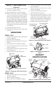
PREVENTATIVE MAINTENANCE To ensure that the heater continues to work properly, it is necessary to periodically clean the combustion chamber, the burner and the fan. WARNING The following steps must be carried out before servicing the heater: turn the heater off, following the instructions in the previous section; disconnect the plug from the power supply and wait for the heater to cool. Every 50 hours of use it is necessary to: • Dismantle the filter cartridge, remove it and clean it with clean fuel oil.
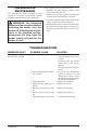
TROUBLESHOOTING Continued OBSERVED FAULT POSSIBLE CAUSE SOLUTION The fan comes on but the flame does not light or does not remain lit 1. Ignitor is not functioning 1. A) Check the connections of the ignition cables to the electrodes and transformer B) Check the position of the electrodes and the distance between them, in accordance with the diagram on page 7 C) Check that the electrodes are clean D) Replace the ignition transformer 2. Replace the flame control 3.
DIAGRAMS HEATER FUNCTIONING DIAGRAM 1 2 3 4 6 5 7 8 9 10 13 11 12 1. Combustion chamber 2. Anti-wind flue connection 3. Burner 4. Nozzle 5. Fuel circuit 6. Fuel pump 7. Electric fuel valve 8. Motor 9. Fan 10. Cable winding bracket 11. Fuel filter 12. Fuel tank 13. Control panel ELECTRIC CONTROL PANEL touopera ION: Ho ani ch. Ketion. t wh ma Do ile com ls, ep chi no bus clothin ldren,t tibl ! es g and away. PR Calien EC AU en te CIÓ Maoperaccuand N: anintengaión. Noo est ma y co les a los tocar.
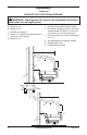
DIAGRAMS Continued EXHAUST PIPE POSITIONING DIAGRAM WARNING: The diagrams are typical; the installation of the flue must meet current legal norms. 1. Anti-wind device fitted with the heater 2. Horizontal crosspiece with a minimum upwards angle of at least 5°, minimum 1" up for every 12" of horizontal travel 3. Flue with minimum internal dimensions of 8" x 8" 4. Anti-explosion/flue inspection shutter 5. External buffer wall 6. H-shape draw activator A. B. C. D. Minimum 3 ft. Minimum 3 ft.
DIAGRAMS Continued ELECTRIC WIRING DIAGRAM FU IT LI EV FO FA Fuse 6A 160-IF 10A 280-IF High voltage transformer Safety thermostat Solenoid valve Photocell Fan thermostat CO MV ST IN TA RE AP Capacitor Fan motor Power light Switch Ambient thermostat socket Relay Control box REGULATION OF COMBUSTION AIR SHUTTER ADJUSTMENT Air Shutter 160-IF 280-IF A=19/32" (15mm) A=5/16" (8mm) A 114909-01A www.desatech.
ILLUSTRATED PARTS BREAKDOWN 10 4 9 28 33 6 20 19 www.desatech.
PARTS LIST This list contains replaceable parts used in your heater. When ordering parts, be sure to provide the correct model and serial numbers (from the model plate), then the part number and description of the desired part. KEY PART NUMBER NO.
ILLUSTRATED PARTS BREAKDOWN AND PARTS LIST CONTROL BOX FOR 160-IF, 280-IF 5 4 15 2 6 8 3 1 16 7 20 17 12 19 18 9 11 13 10 14-1 14-3 KEY 12 14-2 14-4 PART NUMBER NO.
ILLUSTRATED PARTS BREAKDOWN AND PARTS LIST FUEL FILTER ASSEMBLY FOR 160-IF, 280-IF 8 7 6 9 5 4 1 10-1 2 1 10-2 11 10-3 11 10-5 3 10-4 KEY PART NUMBER NO.
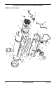
ILLUSTRATED PARTS BREAKDOWN AND PARTS LIST MOTOR, FUEL PUMP AND BURNER COMPONENTS FOR 160-IF, 280-IF 3 Blue Mark 2 4 25 25 6 5 30 29 18 21 20 17 1 12 7-1 11 7-2 19 10 26 24 28 23 22 16 15 9 13 11 12 8 27 14 KEY 14 PART NUMBER NO.
SPECIFICATIONS Model Size 160-IF 280-IF Maximum Output Rating (Btu/Hr) 158,000 278,000 Net Output Rating (Btu/Hr) 133,000 234,400 Fuel Use only kerosene, #1/#2 diesel/fuel oil, JET A or JP-8 fuels* Fuel Tank Capacity (U.S. Gal./Liters) 17/65 28/105 Fuel Consumption (Gal. Per Hr/Liters Per Hr) 1.27/4.81 2.22/8.40 Pump Pressure (psi) 145 174 Electric Requirements 120 V/60 HZ (Same Both Models) Amperage (Normal Run) 4.8 8.
WARRANTY AND REPAIR SERVICE KEEP THIS WARRANTY Model No. Serial No. Date of Purchase (To be filled in by purchaser) LIMITED WARRANTY DESA Heating Products warrants this product and any parts thereof, to be free from defects in materials and workmanship for one (1) year from the date of first purchase when operated and maintained in accordance with instructions. This warranty is extended only to the original retail purchaser, when proof of purchase is provided.
CALENTADOR PORTÁTIL DE AIRE FORZADO VENTILADO MANUAL DEL PROPIETARIO MODELOS: 160-IF, 280-IF IMPORTANTE: Lea y comprenda este manual antes de ensamblar, encender o dar servicio al calentador. El uso inadecuado del calentador puede causar lesiones graves. Conserve este manual para referencias futuras. TABLA DE CONTENIDO Información de seguridad .................................... 2 Desempaque ...................................................... 3 Identificación del producto ..............................
INFORMACIÓN DE SEGURIDAD ADVERTENCIA: este producto contiene y/o genera químicos que el Estado de California reconoce que causan cáncer, defectos de nacimiento u otros daños relacionados con la reproducción. IMPORTANTE: lea este manual del propietario cuidadosa y completamente antes de intentar ensamblar, operar o dar servicio a este calentador.
INFORMACIÓN DE SEGURIDAD Tubo de salida de humos Conexión del conducto de humos Continuación 12. Al mover o almacenar el calentador, debe colocarse en una posición nivelada para evitar que se derrame el combustible. 13. Use el calentador solamente de acuerdo con las ordenanzas y códigos locales. 14. Nunca use gasolina, drenajes de cigüeñal, nafta, solventes de pintura, alcohol u otros combustibles altamente inflamables. 15.
IDENTIFICACIÓN DEL PRODUCTO Salida de aire caliente Conexión del conducto de humos Cubierta superior Resguardo del ventilador Cubierta inferior Panel de Cable de control alimentación Tapa del tanque de combustible Figura 4. Calentador portátil de aire forzado ventilado COMBUSTIBLES ADVERTENCIA: use solamente keroseno, diesel/aceite combustible #1 ó #2, combustible de aviación JET A o JP-8 para evitar riesgos de incendio o explosión.
FUNCIONAMIENTO DEL TERMOSTATO MANTENIMIENTO PREVENTIVO El calentador solamente puede funcionar de manera automática cuando hay un termostato conectado a él fijando el cable a las terminales 2 y 3 del enchufe (4 en la figura Panel de control eléctrico, página 7). Para asegurar que el calentador continúe funcionando correctamente, es necesario limpiar la cámara de combustión, el quemador y el ventilador de manera periódica.
SOLUCIÓN DE PROBLEMAS Continuación FALLA OBSERVADA POSIBLE CAUSA El ventilador arranca pero la llama no se enciende o no se mantiene encendida. 1. El encendedor no está funcio- 1. A) Revise las conexiones de nando. los cables de encendido a los electrodos y transformador. B) Revise la posición de los electrodos y la distancia entre ellos, de acuerdo con el diagrama en la página 7. C) Verifique que los electrodos estén limpios. D) Reemplace el transformador de encendido. 2. Reemplace el control de llama.
DIAGRAMAS DIAGRAMA DE FUNCIONAMIENTO DEL CALENTADOR 1 2 3 4 6 5 7 8 9 1. 2. 3. 4. 5. 10 6. 7. 8. 11 9. 10. 11. 12. 13. 13 12 Cámara de combustión Conexión de protección contra viento del conducto de humos Quemador Boquilla Circuito de combustible Bomba de combustible Válvula de combustible eléctrica Motor Ventilador Soporte de devanado de cables Filtro de combustible Tanque de combustible Panel de control PANEL DE CONTROL ELÉCTRICO 1. Botón de restablecimiento 2.
DIAGRAMAS Continuación DIAGRAMA DE COLOCACIÓN DEL TUBO DE SALIDA DE LOS GASES ADVERTENCIA: los diagramas son típicos; la instalación del conducto de humos debe cumplir con las normas legales vigentes. 1. Dispositivo de protección contra el viento conectado al calentador 2. Pieza cruzada horizontal con un ángulo mínimo hacia arriba de al menos 5°, un mínimo de 2,54 cm (1 pulgada) por cada 30,48 cm (12 pulgadas) de desplazamiento horizontal 3.
DIAGRAMAS Continuación DIAGRAMA DEL CABLEADO ELÉCTRICO FU IT LI EV FO FA Fusible 6A 160-IF 10A 280-IF Transformador de alto voltaje Termostato de seguridad Válvula de solenoide Fotocélula Termostato de ventilador CO MV ST IN TA RE AP Condensador Motor de ventilador Luz de alimentación Interruptor Toma para el termostato ambiental Relé Caja de control REGULACIÓN DEL AJUSTE DEL CONTROLADOR DE AIRE DE COMBUSTIÓN Controlador de aire 160-IF 280-IF A= 15 mm (19/32 de pulgada) A= 8 mm (5/16 de pulgada) A
CLASIFICACIÓN ILUSTRADA DE PIEZAS 10 4 9 28 33 6 20 19 www.desatech.
LISTA DE PIEZAS Esta lista contiene las piezas reemplazables utilizadas en el calentador. Al ordenar las partes, asegúrese de proporcionar el número de modelo y número de serie correctos (de la placa del modelo), después el número de parte y descripción de la parte deseada. CLAVE NÚMERO DE PIEZA NO.
CLASIFICACIÓN ILUSTRADA DE PIEZAS Y LISTA DE PIEZAS CAJA DE CONTROL PARA LOS MODELOS 160-IF, 280-IF 5 4 15 2 6 8 3 1 16 7 20 17 12 19 18 11 13 9 10 14-1 14-3 CLAVE NÚMERO DE PIEZA NO.
CLASIFICACIÓN ILUSTRADA DE PIEZAS Y LISTA DE PIEZAS ENSAMBLAJE DEL FILTRO DE COMBUSTIBLE PARA LOS MODELOS 160-IF, 280-IF 8 7 6 9 5 4 1 10-1 2 1 10-2 11 10-3 11 10-5 3 10-4 CLAVE NÚMERO DE PIEZA NO.
CLASIFICACIÓN ILUSTRADA DE PIEZAS Y LISTA DE PIEZAS MOTOR, BOMBA DE COMBUSTIBLE Y COMPONENTES DE QUEMADOR PARA LOS MODELOS 160-IF, 280-IF (punto azul) 3 Blue Mark 2 4 25 25 6 5 30 29 18 21 20 17 1 12 7-1 11 7-2 19 10 26 24 28 23 22 16 15 9 13 11 12 8 27 14 14 CLAVE NÚMERO DE PIEZA NO.
ESPECIFICACIONES Tamaño del modelo Potencia nominal de salida máxima (BTU/h) Potencia nominal de salida neta (BTU/h) Combustible Capacidad del tanque de combustible (Galones EE.UU.
GARANTÍA Y SERVICIO DE REPARACIÓN GUARDE ESTA GARANTÍA N° de modelo N° de serie Fecha de compra (Para ser llenado por el comprador) GARANTÍA LIMITADA DESA Heating Products (productos de calefacción de DESA) garantiza que este producto y todas sus piezas están libres de defectos en los materiales y la mano de obra durante un (1) año a partir de la primera compra, siempre que se hayan operado y mantenido de acuerdo con las instrucciones.
APPAREIL DE CHAUFFAGE À AIR FORCÉ PORTABLE À CONDUIT D’ÉVACUATION MANUEL D’UTILISATION MODÈLES: 160-IF, 280-IF IMPORTANT : lisez et comprenez ce manuel avant d’assembler, d’allumer ou de réparer l’appareil de chauffage. Une mauvaise utilisation de l’appareil de chauffage peut causer des blessures graves. Conservez ce manuel pour référence future. TABLE DES MATIÈRES Information relative à la sécurité ......................... 2 Déballage ...........................................................
INFORMATION RELATIVE À LA SÉCURITÉ AVERTISSEMENT : cet appareil contient ou produit des produits chimiques déterminés par l’État de Californie comme cancérigènes et pouvant causer des malformations congénitales et d’autres problèmes liés à la reproduction. IMPORTANT : lisez attentivement et entièrement ce manuel d’utilisation avant de tenter d’assembler, de faire fonctionner ou de réparer cet appareil de chauffage.
INFORMATION RELATIVE À LA SÉCURITÉ Tuyau de la canalisation d’air Connexion de la canalisation d’air Suite 13. Utilisez lʼappareil de chauffage en respectant les règlements et les normes locales. 14. Nʼutilisez jamais dʼessence, dʼhuile de vidange de carter, de naphte, de solvant à peinture, dʼalcool ou autre combustible hautement inflammable. 15. Nʼutilisez jamais lʼappareil de chauffage dans des endroits où de lʼessence, du solvant à peinture ou dʼautres vapeurs hautement inflammables sont présents. 16.
IDENTIFICATION DU PRODUIT Sortie d’air chaud Connexion de la canalisation d’air Habillage supérieur Grille de protection du ventilateur Partie inférieure de l’habillage Panneau de Cordon contrôle électrique Bouchon du réservoir de carburant Figure 4 - Appareil de chauffage à air forcé portable à conduit d’évacuation COMBUSTIBLES AVERTISSEMENT : n’utilisez que du kérosène, du diesel ou du mazout n° 1 ou n° 2 ou du carburant JET A ou JP-8 afin d’éviter tout risque d’incendie ou d’explosion.
UTILISATION DU THERMOSTAT Lʼappareil de chauffage peut fonctionner automatiquement si un thermostat y est raccordé en connectant le câble aux bornes 2 et 3 de la prise (4 sur le Panneau de contrôle électrique de la page 7). DÉPLACEMENT ET TRANSPORT DE L’APPAREIL DE CHAUFFAGE AVERTISSEMENT : avant de déplacer l’appareil de chauffage, vous devez l’éteindre (voir Pour arrêter l’appareil de chauffage), débranchez la fiche de la prise électrique et attendre que l’appareil de chauffage refroidisse.
DÉPANNAGE Suite PROBLÈME OBSERVÉ CAUSE POSSIBLE SOLUTION Le ventilateur se met en marche mais la flamme ne sʼallume pas ou ne reste pas allumée 1. Lʼallumeur ne fonctionne pas 1. A) Vérifiez les connexions des câbles dʼallumage aux électrodes et au transformateur B) Assurez-vous que la position et lʼécartement des électrodes correspondent au schéma de la page 7 C) Assurez-vous que les électrodes sont propres D) Remplacez le transformateur de lʼallumeur 2. Remplacez le contrôle de flamme 3.
SCHÉMAS SCHÉMA DE FONCTIONNEMENT DE L’APPAREIL DE CHAUFFAGE 1 2 3 4 6 5 7 8 9 10 13 11 12 1. 2. 3. 4. 5. 6. 7. 8. 9. 10. 11. 12. 13. Chambre de combustion Connexion du conduit d’air pare-vent Brûleur Buse d’aération Ligne de carburant Pompe de carburant Vanne de carburant électrique Moteur Ventilateur Enrouleur de cordon Filtre à carburant Réservoir de carburant Panneau de contrôle PANNEAU DE CONTRÔLE ÉLECTRIQUE 6 ! in CAUT touopera ION: Ho ani ch. Ketion.
SCHÉMAS Suite SCHÉMA DE POSITIONNEMENT DU TUYAU D'ÉVACUATION AVERTISSEMENT : les schémas sont génériques; l’installation du conduit d’air doit se faire en respectant les codes en vigueur. 1. Dispositif pare-vent adapté à l’appareil de chauffage 2. Traverse horizontale avec un angle d'au moins 5° vers le haut, soit un rapport de pente de 2,5 cm sur 30 cm (1 po sur 12 po) 3. Conduit d’air de dimensions internes d’au moins 20,32 sur 20,32 cm (8 x 8 po) 4. Volet d’inspection anti-explosion/conduit d’air 5.
SCHÉMAS Suite SCHÉMA DE CÂBLAGE ÉLECTRIQUE FU IT LI EV FO FA Fusible 6A 160-IF 10A 280-IF Transformateur haute tension Thermostat de sécurité Vanne électromagnétique Cellule photoélectrique Thermostat du ventilateur CO MV ST IN TA RE AP Condensateur Moteur du ventilateur Voyant de mise sous tension Interrupteur Connecteur du thermostat ambiant Relais Boîtier de contrôle RÉGLAGE DU VOLET À AIR DE COMBUSTION Volet d’air 160-IF 280-IF A=15 mm (19/32 po) A=8 mm (5/16 po) A 114909-01A www.desatech.
VUE DÉTAILLÉE DES PIÈCES 10 4 9 28 33 6 20 19 www.desatech.
LISTE DES PIÈCES Cette liste contient les pièces de rechange utilisées dans votre appareil de chauffage. Lorsque vous commandez des pièces, assurez-vous de fournir le bon numéro de modèle et les bons numéros de série (se trouvant sur la plaque signalétique), puis le numéro de pièce et la description de la pièce désirée.
VUE DÉTAILLÉE ET LISTE DES PIÈCES BOÎTIER DE CONTRÔLE POUR LE 160-IF ET LE 280-IF 5 4 15 2 6 8 3 1 16 7 20 17 12 19 18 11 13 9 14-1 14-2 10 14-3 14-4 NUMÉRO DE PIÈCE 12 N° 160-IF 280-IF 1 2 3 4 5 6 7 8 9 10 11 12 13 14 115172-01 115172-01 DESCRIPTION 115173-01 115174-01 115175-01 115176-01 115177-01 115178-01 115179-01 115180-01 115181-01 115182-01 115183-01 115184-01 115173-01 115174-01 115175-02 115176-01 115177-01 115178-01 115179-01 115180-01 115181-01 115182-01 115183-01 115184-
VUE DÉTAILLÉE ET LISTE DES PIÈCES ASSEMBLAGE DE FILTRE À CARBURANT POUR LE 160-IF ET LE 280-IF 8 7 6 9 5 4 1 10-1 2 1 10-2 11 10-3 11 10-5 3 10-4 NUMÉRO DE PIÈCE N° 160-IF 280-IF DESCRIPTION 1 2 3 4 5 6 7 8 9 10 10-1 10-2 10-3 10-4 10-5 11 115252-01 115253-01 115193-01 115194-01 115195-01 115196-01 115197-01 115198-01 115199-01 115200-01 115201-01 115202-01 115203-01 115204-01 115205-01 115206-01 115252-01 115253-01 115193-02 115194-01 115195-01 115196-01 115197-01 115198-01 115199-01 11520
VUE DÉTAILLÉE ET LISTE DES PIÈCES COMPOSANTS DU MOTEUR, DE LA POMPE À CARBURANT ET DU BRÛLEUR POUR LE 160-IF ET LE 280-IF (point bleu) 3 Blue Mark 2 4 25 25 6 5 30 29 18 21 20 17 1 12 7-1 11 7-2 19 10 26 24 28 23 22 16 15 9 13 11 12 8 27 14 NUMÉRO DE PIÈCE N° 1 2 3 4 5 6 7 7-1 7-2 8 9 10 11 12 13 14 15 16 17 18 19 20 21 22 23 24 25 26 27 28 29 30 14 160-IF 115207-01 115208-01 115209-01 115210-01 115211-01 115212-01 115213-01 115214-01 115215-01 115216-01 115217-01 115218-01 115219-01
SPÉCIFICATIONS Dimension du modèle Rendement maximum (BTU/h) Rendement net (BTU/h) Carburant 160-IF 280-IF 158 000 278 000 133 000 234 400 Nʼutilisez que du kérosène, du diesel ou du mazout nº 1 ou nº 2 ou du carburant JET A ou JP-8* Capacité du réservoir de carburant (litres/gal U.S.
SERVICE DE GARANTIE ET DE RÉPARATION CONSERVEZ CETTE GARANTIE Numéro de modèle Numéro de série Date de l’achat (à remplir par l’acheteur) GARANTIE LIMITÉE DESA Heating Products garantit ce produit et toutes les pièces quʼil contient contre tout défaut de matériau et de fabrication pour un (1) an à partir de la date dʼachat originale lorsque utilisés et entretenus selon les instructions. Cette garantie ne protège que lʼacheteur au détail dʼorigine lorsquʼune preuve dʼachat est fournie.