GAS LOG VENTED DECORATIVE APPLIANCE OWNER'S OPERATION AND INSTALLATION MANUAL ANSI Z21.
Table of Contents Safety................................................................... 2 Product Identification............................................ 4 Local Codes......................................................... 4 Unpacking............................................................ 4 Optional Product Features................................... 4 Installation ........................................................... 5 Operation...........................................................
safety Continued WARNING: Any change to this log set or its controls can be dangerous. 1. This appliance, as supplied, is only for use with the type of gas indicated on the rating plate. This appliance is convertible for use with propane/LP, using the GA9050A-1 or GA9150A pilot kit. 2. If you smell gas • shut off gas supply • do not try to light any appliance • do not touch any electrical switch; do not use any phone in your building • immediately call your gas supplier from a neighbor’s phone.
Product Identification Grate Steps Grate Hearth Kit Model______________________ Serial Number________________________ Burner Pan Log Set Model________________________ Burner Clamp Burner Manifold Figure 1 - Product Identification (BVDR24 Shown) Unpacking Local Codes Install and use log set with care. Follow all local codes. In the absence of local codes, use the latest edition of The National Fuel Gas Code ANSI Z223.1/NFPA 54*. *Available from: American National Standards Institute, Inc.
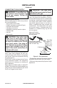
Installation WARNING: The Massachusetts State Board requires all installations be performed by a Licensed Plumber or Gas Fitter. Massachusetts state code requires all vent dampers be welded open or removed. CAUTION: Do not remove the data plates attached to the burner pan. The data plates contain important warranty and safety information.
Installation Continued MODEL DESCRIPTION BVSR18 BVSR24 BVDR18 BVDR24 BVDR30 18" Single Burner 24" Single Burner 18" Dual Burner 24" Dual Burner 30" Dual Burner Btu/Hr Input Btu/Hr Input Minimum Natural Gas Propane/LP Gas Vent Opening 50,000 60,000 55,000 65,000 70,000 40,000 50,000 45,000 55,000 60,000 8" dia. 8" dia. 8" dia. 8" dia. 8" dia.
Installation Continued CONNECTING TO GAS SUPPLY WARNING: A qualified service person must connect log set to gas supply. Follow all local codes. Installation Items Needed Before installing log set, make sure you have the items listed below. • piping (check local codes) • sealant (resistant to propane/LP gas) • equipment shutoff valve • test gauge connection • adjustable (crescent) wrench or pliers • sediment trap • tee joint • pipe wrench CAUTION: Use only new, black iron or steel pipe.
Installation Continued CHECKING GAS CONNECTIONS WARNING: Test all gas piping and connections, internal and external to unit, for leaks after installing or servicing. Correct all leaks at once. Equipment Shutoff Valve Closed Figure 5 - Equipment Shutoff Valve Equipment Shutoff Valve WARNING: Never use an open flame to check for a leak. Apply a noncorrosive leak detection fluid to all joints. Bubbles forming show a leak. Correct all leaks at once.
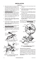
Installation Continued 5. Using thread sealant (resistant to the action of propane/LP gas) on larger end of fitting, screw the burner inlet fitting through hole and into burner manifold. Tighten using a wrench. If using propane/LP gas, see Propane/LP Gas Conversion, page 10. 6. Using burner clamp, screw, and nut provided, assemble clamp to pan (“U” style burners only). This will hold the burner manifold in place. 7.
Installation Continued 2. Attach the pilot gas line to the pilot outlet of the gas control valve and tighten. Connect the thermocouple to the rear of the gas control valve. See Figure 11. Do not overtighten. If using propane/LP gas, see Changing Pilot Orifice, page 11. 3. Install the inlet fitting into the inlet opening of the gas control valve (see Figure 12). Use thread sealant on the male pipe threads. 4. Place the burner pan assembly in the center of the fireplace floor.
Installation Continued Burner Inlet Fitting 1. Remove burner inlet fitting from burner pan assembly. DO NOT remove orifice from this fitting. The propane/LP burner inlet fitting is included in the hardware kit (see Figure 14). 2. Be sure to use correct orifice for your appliance. The hardware kit included with this appliance contains two orifices with a cone-like shape. If you have an 18" set, orifice for burner inlet fitting is red; for a 30" set, it is black.
Installation Continued Testing Burner for Leaks 1. Generously apply noncorrosive leak detection fluid to all connections. WARNING: Never check for gas leaks with open flame. 2. Light the burner with the shutoff valve no more than half open and holding a match slightly in front of the pan (see Lighting Instructions, page 13). 3. Inspect all connections for bubbles, raw gas odor, or flame from any area other than the burner (leaks). If leaks are detected, shut off the gas valve immediately.
Installation Continued Figure 20 - Placement of Top Logs (Mossy Maple Logs Shown) Operation LIGHTING INSTRUCTIONS FOR YOUR SAFETY READ BEFORE LIGHTING WARNING: Keep flue open when operating unit. WARNING: If you do not follow these instructions exactly, a fire or explosion may result causing property damage, personal injury or loss of life. BEFORE LIGHTING smell all around the appliance area for gas. Be sure to smell next to the floor because some gas is heavier than air and will settle on the floor.
Operation Continued Pilot Ignitor ON OFF FROM "PILOT" POSITION SLIGHT PUSH TO TURN OFF PULL PUSH On Off ON OFF 14 Control Knob FROM "PILOT" POSITION SLIGHT PUSH TO TURN OFF PULL PUSH Note: Operation instructions for GA9150A Remote Ready Valve/Pilot Kit will be included with the kit. 1. STOP! Read the safety information, page 13. 2. Make sure equipment shutoff valve is fully open. 3. Press in and turn control knob clockwise to the OFF position. 4. Wait five (5) minutes to clear out any gas.
Inspecting Burners Check pilot flame pattern and burner flame patterns often. PILOT Assembly The pilot assembly is factory preset for proper flame height. Alterations may have occurred during shipping and handling. The pilot is located on back right hand side of burner. The thermocouple should be fully enveloped in flame. Flame should not be lifting off thermocouple element. If your pilot assembly does not meet these requirements: • Access pilot adjustment screw through slot in valve cover.
Troubleshooting WARNING: Turn off log set and let cool before servicing. Only a qualified service person should service and repair log set. Note: All troubleshooting items are listed in order of operation. OBSERVED PROBLEM POSSIBLE CAUSE REMEDY Log set is smoking/sooting excessively (Note: It is natural and unavoidable for vented gas log sets to produce moderate levels of carbon (soot) where flames contact the logs. This is especially true with propane/LP gas.) 1. Poor fuel quality 5.
TROUBLESHOOTING Continued OBSERVED PROBLEM POSSIBLE CAUSE REMEDY When ignitor button is pressed, there is spark at pilot but no ignition (GA9050A-1 Only) 1. Gas supply turned off or equipment shutoff valve closed 2. Control knob not in PILOT position 3. Control knob not pressed in while in PILOT position 4. Air in gas lines when installed 1. Turn on gas supply or open equipment shutoff valve 5. Pilot adjustment screw closed 6. Pilot is clogged 7.
TROUBLESHOOTING Continued WARNING: If you smell gas • Shut off gas supply. • Do not try to light any appliance. • Do not touch any electrical switch; do not use any phone in your building. • Immediately call your gas supplier from a neighbor’s phone. Follow the gas supplier’s instructions. • If you cannot reach your gas supplier, call the fire department. IMPORTANT: Operating log set where impurities in air exist may create odors.
Replacement Parts Note: Use only original replacement parts. This will protect your warranty coverage for parts replaced under warranty. Usually, we will ask you to return the part to the factory. Parts Under Warranty Contact authorized dealers of this product. If they can’t supply original replacement part(s), call DESA Heating, LLC at 1-866-672-6040 for referral information. A list of authorized dealers can be found by visiting www.desatech.com.
Parts Burner Models BVSR18, BVSR24, BVDR18, BVDR24 AND BVDR30 9 9 10 7 12 5 11 5 1 6 8 4 2 13 20 3 www.desatech.
PARTS 5 6 7 8 9 10 11 12 13 901056-01 901059-01 901066-01 901064-02 901064-03 901064-04 901208-01 901208-02 901209-03 901136-01 901136-02 901137-01 901137-02 901137-03 901242-01 101628-01 901430-01 901431-01 901243-01 901243-02 901246-01 901246-02 901246-03 901681-01 901078-01 901076-01 Brass 3/8 FLR x 1/2 FPT Adapter Brass 3/8 FLR x 3/8 FPT Adapter Brass Air Mixer - Natural Gas Natural Gas Injector Natural Gas Injector Natural Gas Injector Burner Manifold Burner Manifold Burner Manifold Burner Pan Bu
Parts This list contains replaceable parts used in your log set. When ordering parts, follow the instructions listed under Replacement Parts on page 19 of this manual.
3 7 PARTS This list contains replaceable parts used in your log set. When ordering parts, follow the 1 instructions listed under Replacement Parts on page 19 of this manual.
PARTS This list contains replaceable parts used in your log set. When ordering parts, follow the instructions listed under Replacement Parts on page 19 of this manual.
NOTES _____________________________________________________ ______________________________________________________ ______________________________________________________ ______________________________________________________ ______________________________________________________ ______________________________________________________ ______________________________________________________ ______________________________________________________ ______________________________________________________ ___________
NOTES _____________________________________________________ ______________________________________________________ ______________________________________________________ ______________________________________________________ ______________________________________________________ ______________________________________________________ ______________________________________________________ ______________________________________________________ ______________________________________________________ ___________
NOTES _____________________________________________________ ______________________________________________________ ______________________________________________________ ______________________________________________________ ______________________________________________________ ______________________________________________________ ______________________________________________________ ______________________________________________________ ______________________________________________________ ___________
Warranty KEEP THIS WARRANTY Model (located on product or identification tag)______________________________ Serial No. (located on product or identification tag)___________________________ Date Purchased ___________________________ Keep receipt for warranty verification.