
Gas Heater User Manual


www.desatech.com
901746-01E10
INSTALLATION
Continued
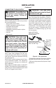
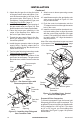
2. Attach the pilot gas line to the pilot outlet
of the gas control valve and tighten. Con-
nect the thermocouple to the rear of the
gas control valve. See Figure 11. Do not
overtighten. If using propane/LP gas, see
Changing Pilot Orice, page 11.
3. Install the inlet tting into the inlet opening of
the gas control valve (see Figure 12). Use
thread sealant on the male pipe threads.
4. Place the burner pan assembly in the
center of the replace oor. Make sure
the front of pan faces forward.
5. Thread the gas supply tting to the re-
place gas supply pipe. Adjust to most
convenient position.
6. Install the gas connector tube to the gas
supply tting. Carefully shape tube to
attach to adapter tting. Be careful not to
cause kinks in tube.
7. Test for leaks following instructions under
Testing Burner for Leaks, page 12.
8. Retighten and adjust the location of the
gas control as necessary. The gas control
should be level, with the control rod to the
front.
To convert to propane/LP gas, the burner inlet
tting and pilot orice must be replaced. The
propane/LP burner inlet tting is supplied with
orice installed for a 24" log set. If you have
an 18" or 30" log set, you must change this
orice also. See Figure 1, page 4 for product
identication.
9. Attach cover to burner pan using screws
provided.
10. Install thermocouple, pilot, and ignitor onto
valve cover as shown in Figure 13. Use
the provided screws.
11. Push the control rod extension onto the
“D” shaped control rod through the center
hole in the cover.
12. Install the control position decal and con-
trol knob making sure to align the marks
with the correct stop positions of the gas
control. Pilot position will allow the knob
to push in about 1/2". Align the decals in
the pilot position.
Note: Pilot valve adjustment screw may need
to be opened. See Inspecting Burners, page
15 for instructions.
Figure 11 - Gas Control Valve with
Thermocouple and Pilot
Pilot
and
Line
Thermocouple
and Line
Gas Control
Valve
Figure 12 - Installing Inlet Fitting and
Gas Connector Tube
Gas
Connector
Tube
Gas Inlet
Fitting
Gas Control
Valve
Inlet
Opening
Figure 13 - Installing Cover, Control
Knob and Piezo Ignitor
Piezo Ignitor
Valve Cover
Control Rod
Extension
Control
Knob
Ignitor
Screw
Thermocouple
Pilot