
User Guide


www.fmiproducts.com
124970-01A10
55
5
/
8
"
39
3
/
8
"
34
1
/
2
"
27
3
/
4
"
0" CLEARANCE
*10
1
/
2
"
*10
1
/
2
"
* These dimensions allow for min. Clearances to
a 45° projected side wall. However, clearances
to projected mantel trims and facings are allowed
within a min. Of 16" to a perpenducular wall as
shown in Figure 4, on page 9.
FOR 32" MODELS
INSTALLATION
Continued
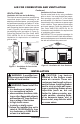
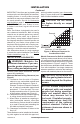
Figure 5 - Minimum Mantel Clearances
for Built-In Installation
Supplied
Firebox Hood
Must Be Used
at All Times
Wire-mesh
Screen
Firebox
Noncombustible
Material May
Project Off this
Surface above
the Firebox Hood
Mantel Shelf
Note: Any portion of the
mantel shelf must NOT
extend beyond this profile.
12" 16" 20"
1
1
/
2
"
6
3
/
4
"
12"
Note: All vertical
measurements are
from top of fireplace
hood opening to
bottom of mantel shelf.
These minimum
clearances replace any
other recommended
clearances supplied
with your ANSI Z21.11.2
approved gas logs.
Wa ll board or facing
material (above
firebox) may be of
combustible material,
including decorative
mantel ornaments or
other similar projec-
tions off of the facing
material.
Framing
Material
Built-in Installation
Model
Front Width
(Inside to Inside) Height
Depth
(Min.)
32" 34
7
/
8
" 36
3
/
4
" 16
1
/
4
"
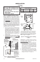
Figure 6 - Rough Opening for Installing
in Wall
Depth
(Minimum)
Width
(Inside to Inside)
Height
Figure
6a
Figure
6b
NOTICE: If your installation does
not meet the minimum clear-
ances shown, you must do one
-
BUILT-IN FIREBOX INSTALLATION
Built-in installation of this rebox involves
installing rebox into a framed-in enclosure.
This makes the front of rebox ush with wall.
Optional brass trim accessories are available
(see Accessories, page 17). The brass trim
will extend past sides of rebox approximately
1/2". This will cover the rough edges of the
wall opening. If installing a mantel above the
rebox, you must follow the clearances shown
in Figure 6. Follow the instructions below to
install the rebox in this manner.
1. Frame in rough opening. The rebox fram-
ing should be constructed of 2 x 4 lumber
or heavier. Use dimensions in Table 1
and rough opening layout in Figure 6a.
Adjust framing so that firebox flushes
with nished wall surface. If installing in a
corner, use dimensions in Figures 6b for
rough opening.
2. Install gas piping to rebox location. See In-
stalling Gas Line, page 11 and Connecting
to Gas Supply in log set owner’s manual.
IMPORTANT: If installing blower accessory
(circulating models with louvers only), see
Hard-Wiring Firebox, page 15.
3. Carefully set rebox in front of rough open-
ing with back of rebox inside wall open-
ing. IMPORTANT: If installing a perimeter
trim kit, see instructions included with
trim accessory. You must install shoulder
screws from trim kit now.
4.
Carefully insert rebox into rough opening.
5. Attach rebox to wall studs using nails
or wood screws through holes in nailing
ange (see Figure 7 on page 11).