
User Guide

www.fmiproducts.com
124970-01A12
INSTALLATION
Continued
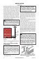
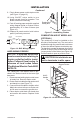
Locate the recessed knockout in one of the
rebrick sidewall liners (see Figure 8 on page
11 and Figure 9). Firmly tap the center of the
knockout with a chisel until it is released.
Carefully chisel the rough edges of the hole
you have made to smooth edges. This hole
will line up with the hole in the outer casing.
Locate the recessed knockout in one of the
rebrick sidewall liners (see Figure 8 on page
11 and Figure 9). Firmly tap the center of the
knockout with a chisel until it is released.
Carefully chisel the rough edges of the hole
to smooth edges. This hole will line up with
the hole in the outer casing.
CAUTION: Do not use exces-
sive force to remove the knock-
Figure 9 - Location of Knockout for Gas
Line
Knockout Chisel
Firebrick Side Wall
Remove
this Area
Side
View
NOTICE
There are two (2) blower accessory options for
use in the vent-free reboxes. Blower acces-
sory models are BK and BK3. Model BK is a
rotary squirrel cage type blower with magnetic
attachment and variable speed control. The
BK3 is a triple fan blower system with an on/
off rocker switch.
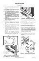
The blower must be installed by removing the
lower face panel and placing blower into its
proper mounting position.
Decide which way you intend to gain access
into the bottom rear of the rebox to install
the blower accessory. The lower front panel
can be removed easily by snapping out the
front with a at blade screwdriver. Use cau-
tion not to scratch any surfaces. Models with
louvered front panels can also be removed by
inserting ngertips between slots and gently
pulling out. DO NOT FORCE. The panels are
actually held in place by means of a retention
dimple embossed on the edge of removable
panels.
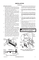
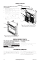
electrical outlet installed in the
Duplex Electrical Outlet
Figure 10 - Accessing Duplex Electrical
Outlet Installed in Bottom Right Side of
Firebox
INSTALLING OPTIONAL BLOWER
ACCESSORIES
NOTICE:-
-
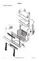
Note: Appearance of rebox may vary
depending on model.