
User Guide

www.fmiproducts.com
124970-01A 15
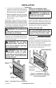
9. Plug in blower power cord to duplex outlet
(see Figure 10, page 12).
10. Using ON/OFF rocker switch to turn
blower on and check for operation. Turn
blower off before continuing.
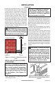
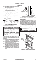
11. Peel off backing paper and stick supplied
wiring diagram decal on rebox bottom
approximately 12" in from of blower (see
Figure 16).
12. Replace all panels and/or brick bottom
panel if previously removed.
INSTALLATION
Continued
Black
110/115
V . A.C.
Blower
Motor
No. 1
Black
Hot
Nuetral
ON/OFF
Panel Switch
Blower
Motor
No. 2
Blower
Motor
No. 3
Figure 16 - BK3 Wiring Diagram
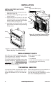
HARD-WIRING FIREBOX
-
The National Electric Code ANSI/
NFPA 70.
The “Handy Box” with duplex outlet is pro-
vided in the rebox located in the lower right
base area.
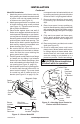
1. Remove screw holding duplex outlet cover
to handy box. Remove duplex outlet.
2. Route electrical cable through strain relief
and handy box (see Figure 17).
3. Connect electrical cable to duplex outlet.
Match wire colors to those on duplex out-
let. Be sure to connect the ground wire.
4. Place duplex outlet back into handy box
and secure with screws. Replace outlet
cover.
Strain Relief
Duplex Box/
Handy Box
Figure 17 - Hard-Wiring Firebox
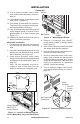
COMBUSTION AIR KIT MODEL AK4
The outside air kit may be installed on the
left side of the replace only. The vent can be
installed through any outside wall a minimum
of three feet below replace termination cap.
The handle to operate the damper door for the
outside air inlet will be located inside the left
“screen pocket” of the rebox (see Figure 18).
Pull the handle to open or push to close.
CAUTION: Air inlet ducts are
Figure 18 - Air Kit Handle Location
Air Kit
Handle
Screen Pocket