
OWNER'S OPERATION AND INSTALLATION MANUAL BLUE-FLAME VENT-FREE NATURAL GAS HEATER CGN20, CGN20L, RN30D


8
103568
VENT-FREE NATURAL GAS HEATERS
BLUE-FLAME CGN20, CGN20L AND RN30D
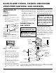
Figure 11 - Installing Bottom Mounting
Screws
Figure 10 - Mounting Heater Onto
Mounting Bracket
INSTALLING TO
WALL
Continued
Mounting
Bracket
(attached
to wall)
Horizontal
Slots
Stand-Out
Tab
CONNECTING TO
GAS SUPPLY
NOTICE: A qualified service per-
son must connect heater to gas
supply. Follow all local codes.
WARNING: Never connect
heater to private (non-utility) gas
wells. This gas is commonly
known as wellhead gas.
IMPORTANT:
Check gas line pressure be-
fore connecting heater to gas line. Gas line
pressure must be no greater than 14 inches
of water. If gas line pressure is higher,
heater regulator damage could occur.
Installation must include a manual shutoff
valve, union, and plugged 1/8" NPT tap.
Locate NPT tap within reach for test gauge
hook up. NPT tap must be upstream from
heater (see Figure 12).
CAUTION: Use only new,
black iron or steel pipe. Inter-
nally-tinned copper tubing may
be used in certain areas. Check
your local codes. Use pipe of 1/2"
diameter or greater to allow
proper gas volume to heater. If
pipe is too small, undue loss of
pressure will occur.
Typical Inlet Pipe Diameters
20,000 Btu/Hr models 3/8" or greater
30,000 Btu/Hr models 1/2" or greater
Figure 12 - Gas Connection
* An A.G.A. design certified manual shutoff valve with 1/8" NPT tap is an acceptable
alternative to test gauge connection. Purchase the optional A.G.A. design certified manual
shutoff valve from your dealer. See Accessories, page 15.
Tee Joint
Reducer
Bushing to
1/8" NPT
1/8" NPT
Plug Tap
Pressure
Regulator
Test
Gauge
Connection *
Sediment
Trap
Tee Joint
Pipe Nipple
Cap
Heater
Cabinet
3/8" NPT
Pipe Nipple
Note:
Burner bracket
not shown for clarity
Manual Shutoff
Valve *
Typical Inlet
Pipe From
Gas Meter
(4" W.C. to 10.5"
W.C.
Pressure)
Ground Joint
Union
3" Minimum
Placing Heater On Mounting
Bracket
1. Locate two horizontal slots on back
panel of heater.
2. Place heater onto mounting bracket.
Slide horizontal slots onto stand-out
tabs on mounting bracket.
Installing Bottom Mounting
Screws
1. Locate two bottom mounting holes.
These holes are near bottom on back
panel of heater (see Figure 11).
2. Mark screw locations on wall.
3. Remove heater from mounting bracket.
4. If installing bottom mounting screws
into hollow or solid wall, install wall
anchors. Follow steps 1 through 4 un-
der Attaching To Wall Anchor Method,
page 7.
If installing bottom mounting screw
into wall stud, drill holes at marked lo-
cations using 9/64" drill bit.
5. Replace heater onto mounting bracket.
6. Place spacers between bottom mount-
ing holes and wall anchor or drilled
hole.
7. Hold spacer in place with one hand.
With other hand, insert mounting screw
through bottom mounting hole and
spacer. Place tip of screw in opening
of wall anchor or drilled hole.
8. Tighten both screws until heater is
firmly secured to wall. Do not over
tighten.
Note:
Do not replace front panel at this
time. Replace front panel after making
gas connections and checking for leaks
(see pages 8-9).