VENT-FREE INFRARED NATURAL GAS HEATER OWNER’S OPERATION AND INSTALLATION MANUAL ® Models: CGN18RA and CGN30D WARNING: If the information in this manual is not followed exactly, a fire or explosion may result causing property damage, personal injury, or loss of life. — Do not store or use gasoline or other flammable vapors and liquids in the vicinity of this or any other appliance. — WHAT TO DO IF YOU SMELL GAS • Do not try to light any appliance.
CONTENTS SECTION PAGE Safety Information ......................................................................... 2 Product Identification .................................................................... 4 Local Codes ................................................................................... 4 Unpacking ...................................................................................... 4 Product Features ............................................................................
SAFETY INFORMATION Continued WARNING ICON G 001 WARNINGS Continued WARNING: Any change to this heater or its controls can be dangerous. 1. Use only natural gas. Do not convert heater to use different fuel type. 2. If you smell gas • shut off gas supply • do not try to light any appliance • do not touch any electrical switch; do not use any phone in your building • immediately call your gas supplier from a neighbor’s phone.
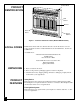
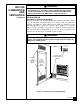
Control Knob PRODUCT IDENTIFICATION Grill Guard Burners Front Panel Heater Cabinet COMFORT GLOW PLAQUE FRONT-NON THERMO GRH/PV 006A Figure 1 - Vent-Free Natural Gas Heater (Model CGN30D Shown) LOCAL CODES Install and use heater with care. Follow all local codes. In the absence of local codes, use the latest edition of National Fuel Gas Code ANSI Z223.1, also known as NFPA 54*. *Available from: American National Standards Institute, Inc.
AIR FOR COMBUSTION AND VENTILATION WARNING ICON G 001 WARNING This heater shall not be installed in a confined space unless provisions are provided for adequate combustion and ventilation air. Read the following instructions to insure proper fresh air for this and other fuel-burning appliances in your home. Today’s homes are built more energy efficient than ever. New materials, increased insulation, and new construction methods help reduce heat loss in homes.
AIR FOR COMBUSTION AND VENTILATION Continued DETERMINING AIR FLOW FOR HEATER LOCATION Determining if You Have a Confined or Unconfined Space Use this worksheet to determine if you have a confined or unconfined space. Space: Includes the room in which you will install heater plus any adjoining rooms with doorless passageways or ventilation grills between the rooms. 1. Determine the volume of the space (length x width x height). Length x Width x Height = ___________________ cu. ft.
AIR FOR COMBUSTION AND VENTILATION Continued WARNING ICON G 001 WARNING If the area in which the heater may be operated is smaller than that defined as an unconfined space, provide adequate combustion and ventilation air by one of the methods described in the National Fuel Gas Code, ANSI Z223.1, 1992, Section 5.3. VENTILATION AIR Ventilation Air From Inside Building This fresh air would come from an adjoining unconfined space.
AIR FOR COMBUSTION AND VENTILATION Continued VENTILATION AIR (Continued) Ventilation Air From Outdoors Provide extra fresh air by using ventilation grills or ducts. You must provide two permanent openings: one within 12" of the ceiling and one within 12" of the floor. Connect these items directly to the outdoors or spaces open to the outdoors. These spaces include attics and crawl spaces. Follow the National Fuel Gas Code NFPA 54/ANSI Z223.1, Section 5.
INSTALLING TO WALL NOTICE A qualified service person must install heater. Follow all local codes. CHECK GAS TYPE Use only natural gas. If your gas supply is not natural, do not install heater. Call dealer where you bought heater for proper type heater. INSTALLATION ITEMS Before installing heater, make sure you have the items listed below.
INSTALLING TO WALL Continued WARNING ICON G 001 CAUTION If you install the heater in a home garage • heater pilot and burner must be at least 18 inches above floor • locate heater where moving vehicle will not hit it For convenience and efficiency, install heater • where there is easy access for operation, inspection, and service • in coldest part of room An optional fan kit is available from your dealer. See Accessories, page 27. If planning to use fan, locate heater near an electrical outlet.
INSTALLING TO WALL Continued INSTALLING HEATER TO WALL Mounting Bracket The mounting bracket is located on back panel of heater. It has been taped there for shipping. Remove mounting bracket from back panel. Mounting Bracket Figure 5 - Mounting Bracket Location Removing Front Panel Of Heater 1. Remove two screws near bottom corners of front panel. 2. Lift straight up on grill guard until it stops. Grill guard will slide up about 1/4". 3. Pull bottom of front panel forward, then down.
INSTALLING TO WALL Marking Screw Locations 1. Tape mounting bracket to wall where heater will be located. Make sure mounting bracket is level. Continued WARNING ICON G 001 WARNING Maintain minimum clearances shown in Figure 7. If you can, provide greater clearances from floor and joining wall. 2. Mark screw locations on wall (see Figure 7). Note: Only mark last hole on each end of mounting bracket. Insert mounting screws through these holes only. 3. Remove tape and mounting bracket from wall.
INSTALLING TO WALL 4. For thin walls (1/2" or less), insert red key into wall anchor. Push red key to “pop” open anchor wings. IMPORTANT: Do not hammer key! For thick walls (over 1/2" thick) or solid walls, do not pop open wings. Continued Figure 9 - Popping Open Anchor Wings For Thin Walls 5. Place mounting bracket onto wall. Line up last hole on each end of bracket with wall anchors. 6. Insert mounting screws through bracket and into wall anchors. 7.
CONNECTING TO GAS SUPPLY NOTICE A qualified service person must connect heater to gas supply. Follow all local codes. WARNING ICON WARNING G 001 Never connect heater to private (non-utility) gas wells. This gas is commonly known as wellhead gas. IMPORTANT: Check gas line pressure before connecting heater to gas line. Gas line pressure must be no greater than 14 inches of water. If gas line pressure is higher, heater regulator damage could occur.
CONNECTING TO GAS SUPPLY IMPORTANT: Hold pressure regulator with wrench when connecting it to gas piping and/or fittings. Continued Pressure Regulator 1/2" NPT Pipe Nipple Heater Cabinet Ground Joint Union Tee Joint Test Gauge Connection * Reducer Bushing to 1/8" NPT Manual Shutoff Valve * From Gas Meter (7" W.C. to 10.5" W.C. Pressure) 1/8" NPT Plug Tap Tee Joint Sediment Trap Pipe Nipple 3" Minimum Cap Figure 12 - Gas Connection * An A.G.A.
CHECKING GAS CONNECTIONS 4. Check all joints of gas supply piping system. Apply mixture of liquid soap and water to gas joints. Bubbles forming show a leak. 5. Correct all leaks at once. Continued 1. Close manual shutoff valve (see Figure 13). 2. Pressurize supply piping system by either using compressed air or opening main gas valve located on or near gas meter. 3. Check all joints from gas meter to manual shutoff valve (see Figure 14). Apply mixture of liquid soap and water to gas joints.
OPERATING HEATER FOR YOUR SAFETY READ BEFORE LIGHTING WARNING ICON G 001 WARNING If you do not follow these instructions exactly, a fire or explosion may result causing property damage, personal injury or loss of life. A. This appliance has a pilot which must be lighted by hand. When lighting the pilot, follow these instructions exactly. B. BEFORE LIGHTING smell all around the appliance area for gas. Be sure to smell next to the floor because some gas is heavier than air and will settle on the floor.
OPERATING HEATER 4. Wait five (5) minutes to clear out any gas. Then smell for gas, including near the floor. If you smell gas, STOP! Follow “B” in the safety information at the top of page 17. If you don’t smell gas, go to the next step. Continued 5. Press in control knob. Note: You may be running this heater for the first time after hooking up to gas supply. If so, you may need to press in control knob for 30 seconds. This will allow air to bleed from the gas system. 6.
OPERATING HEATER TO SELECT HEATING LEVEL Continued WARNING ICON WARNING G 001 When running heater, set control knob at LOW, MEDIUM, or HIGH locked positions. Never set control knob between locked positions. Poor combustion may result. WARNING ICON G 001 CAUTION Do not try to adjust heating levels by using the manual shutoff valve. 1. Slightly press in control knob and turn counterclockwise to the LOW, MEDIUM, or HIGH positions. IMPORTANT: Release downward pressure while turning control knob.
OPERATING HEATER Continued TO TURN OFF GAS TO APPLIANCE Shutting Off Heater 1. Turn control knob clockwise Clockwise to the OFF position. 2. Turn off all electric power to the appliance if service is to be performed. Shutting Off Burner Only (pilot stays lit) 1. Turn control knob clockwise Clockwise to the PILOT position. MANUAL LIGHTING PROCEDURE 1. Follow steps 1 through 6 under Lighting Instructions, pages 17 and 18. 2. With control knob pressed in, strike match.
INSPECTING BURNER BURNER FLAME PATTERN Figure 20 shows a correct burner flame pattern. Figure 21 shows an incorrect burner flame pattern.
CLEANING AND MAINTENANCE WARNING ICON G 001 WARNING Turn off heater and let cool before cleaning. WARNING ICON G 001 CAUTION You must keep control areas, burner, and circulating air passageways of heater clean. Inspect these areas of heater before each use. Have heater inspected yearly by a qualified service person. Heater may need more frequent cleaning due to excessive lint from carpeting, bedding material, etc.
TROUBLESHOOTING Continued OBSERVED PROBLEM POSSIBLE CAUSE When control knob is pressed in and turned to the PILOT/IGN position, there is spark at ODS/pilot but no ignition 1. Gas supply turned off or manual shutoff valve closed 2. Control knob not pressed in while being turned to PILOT/IGN position 3. Air in gas lines when installed 4. ODS/pilot is clogged 5. Gas regulator setting is not correct ODS/pilot lights but flame goes out when control knob is released 1. Control knob not fully pressed in 2.
TROUBLESHOOTING Continued OBSERVED PROBLEM POSSIBLE CAUSE Burner(s) does not light after ODS/pilot is lit 1. Burner orifice(s) is clogged 2. Burner orifice(s) diameter is too small 3. Inlet gas pressure is too low REMEDY 1. Clean burner orifice(s) (see Cleaning and Maintenance, page 22) or replace burner orifice(s) 2. Replace burner orifice(s) 3. Contact local natural gas company Delayed ignition of burner(s) 1. Manifold pressure is too low 2. Burner orifice(s) is clogged 1.
TROUBLESHOOTING Continued WARNING ICON G 001 WARNING If you smell gas • Shut off gas supply. • Do not try to light any appliance. • Do not touch any electrical switch; do not use any phone in your building. • Immediately call your gas supplier from a neighbor’s phone. Follow the gas supplier’s instructions. • If you cannot reach your gas supplier, call the fire department. IMPORTANT: Operating heater where impurities in air exist may create odors.
SPECIFICATIONS SERVICE HINTS BTU (Variable) Type Gas Ignition Pressure Regulator Setting Inlet Gas Pressure (in. of water) Maximum Minimum Dimensions, Inches (H x W x D) Heater Carton Weight (pounds) Heater Shipping CGN18RA 6,600/12,000/18,000 Natural Only Piezo 6" W.C. CGN30D 6,600/18,000/30,000 Natural Only Piezo 6" W.C. 10.5" 7" 10.5" 7" 23.5 x 18.5 x 8 26 x 20.5 x 9.625 23.5 x 25.9 x 8 26 x 27.75 x 9.
PARTS CENTRALS These Parts Centrals are privately-owned businesses. They have agreed to support our customer’s needs by providing original replacement parts and accessories. Baltimore Electric 1348 Dixwell Avenue Hamden, CT 06514 1-800-397-7553 203-248-7553 Parts Department Master Parts Distributor 1184 Wilson NW Walker, MI 49504 616-791-0505 Fax: 1-616-791-8270 Parts Department Portable Heater Parts 342 N. County Rd.
ILLUSTRATED PARTS BREAKDOWN 11 12 10 Model CGN18RA 14 4 9 6 13 8 HEATER EXPLODED VIEW 7 5 3 6 2 13-1 A B 1 13-16 13-17 C 13-10 13-2 13-11 13-4 13-3 13-12 13-15 13-13 13-5 13-6 13-7 13-14 13-8 13-9 ODS/PILOT BURNER ASSEMBLY 28 101826
PARTS LIST Model CGN18RA This list contains replaceable parts used in your heater. When ordering parts, follow the instructions listed under Replacement Parts on page 26 of this manual. KEY NO.
ILLUSTRATED PARTS BREAKDOWN 11 12 10 Model CGN30D 4 14 15 9 6 8 13 HEATER EXPLODED VIEW 7 5 16 3 6 2 1 A B C 13-16 13-17 13-9 13-1 D E 13-11 13-2 13-4 13-5 13-3 13-12 13-15 13-7 13-13 13-6 13-14 13-18 ODS/PILOT 13-8 13-10 BURNER ASSEMBLY 30 101826
PARTS LIST Model CGN30D This list contains replaceable parts used in your heater. When ordering parts, follow the instructions listed under Replacement Parts on page 26 of this manual. KEY NO.
WARRANTY INFORMATION KEEP THIS WARRANTY Model Serial No. Date Purchased Always specify model and serial numbers when communicating with the factory. We reserve the right to amend these specifications at any time without notice. The only warranty applicable is our standard written warranty. We make no other warranty, expressed or implied.