
OWNER'S OPERATION AND INSTALLATION MANUAL UNVENTED (VENT-FREE) GAS LOG HEATER VRL24NR, VRL24PR, VRL30NR, VRL30PR, CSG3924NR, CSG3924PR, CTB3924NR, CTB3924PR,VRL24NT, VRL24PT, VRL30NT, VRL30PT, CSG3924NT, CSG3924PT, CTB3924NT, CTB3924PT
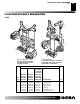

110021-01B
For more information, visit www.desatech.com
For more information, visit www.desatech.com
23
23
WARNING: Turn off heater and let cool before
cleaning.
CAUTION: You must keep control areas, burners,
and circulating air passageways of heater clean. In-
spect these areas of heater before each use. Have
heater inspected yearly by a qualified service person.
Heater may need more frequent cleaning due to exces-
sive lint from carpeting, pet hair, bedding material, etc.
CLEANING BURNER INJECTOR HOLDERS
AND PILOT AIR INLET HOLES
The primary air inlet holes allow the proper amount of air to mix with
the gas. This provides a clean burning flame. Keep these holes clear
of dust, dirt, lint, and pet hair. Clean these air inlet holes prior to each
heating season. Blocked air holes will create soot. We recommend
that you clean the unit every three months during operation and have
heater inspected yearly by a qualified service person.
We also recommend that you keep the burner tubes and pilot
assembly clean and free of dust and dirt. To clean these parts we
recommend using compressed air no greater than 30 PSI. Your local
computer store, hardware store, or home center may carry com-
pressed air in a can. You can use a vacuum cleaner in the blow
position. If using compressed air in a can, please follow the direc-
tions on the can. If you don't follow directions on the can, you could
damage the pilot assembly.
1. Shut off the unit, including the pilot. Allow the unit to cool for
at least thirty minutes.
2. Inspect burners, pilot, and primary air inlet holes on injector
holder for dust and dirt (see Figures 41 or 42).
3. Blow air through the ports/slots and holes in the burners.
4. Check the injector holders located at the end of the burner tubes
again. Remove any large particles of dust, dirt, lint, or pet hair
with a soft cloth or vacuum cleaner nozzle.
5. Blow air into the primary air holes on the injector holders.
6. In case any large clumps of dust have now been pushed into
the burner repeat steps 3 and 4.
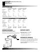
Clean the pilot assembly also. A yellow tip on the pilot flame
indicates dust and dirt in the pilot assembly. There is a small pilot
air inlet hole about two inches from where the pilot flame comes out
of the pilot assembly (see Figure 43). With the unit off, lightly blow
air through the air inlet hole. The access hole for propane/LP pilot
is on the front of the burner carriange as shown in Figure 43. The
access hole for natural pilot is behind the pilot bracket on the top of
burner carriage (see Figure 43). You may blow through a drinking
straw if compressed air is not available.
CLEANING AND
MAINTENANCE
LOGS
• If you remove logs for cleaning, refer to Installing Logs, pages
15 and 16, to properly replace logs.
• Replace log(s) if broken or chipped (dime-sized or larger).
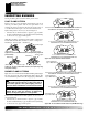
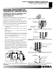
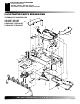
CLEANING AND MAINTENANCE
Cleaning Burner Injector Holders and Pilot Air Inlet Holes
Figure 41 - Injector Holder On Outlet Burner Tube - Rear Burner
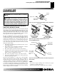
Figure 43- Cleaning Pilot Air Inlet Hole (Your pilot may vary from
pilots shown)
Figure 42 - Injector Holder On Outlet Burner Tubes -
Front and Middle Burners
Burner Tube
Primary Air
Inlet Holes
Injector
Holder
Injector
Holder
Primary Air Inlet Holes
Pilot Air
Inlet Hole
Pilot Assembly
Ports/Slots
Primary Air Inlet Holes
Injector
Holder
YELLOW FLAME
(CTB Models)
BLUE FLAME
(VRL and CSG Models)
Access Hole
for Cleaning
Natural Pilot
Access Hole
for Cleaning
Propane/LP
Pilot
Pilot Bracket