
OWNER'S OPERATION AND INSTALLATION MANUAL UNVENTED (VENT-FREE) GAS LOG HEATER VRL24NR, VRL24PR, VRL30NR, VRL30PR, CSG3924NR, CSG3924PR, CTB3924NR, CTB3924PR,VRL24NT, VRL24PT, VRL30NT, VRL30PT, CSG3924NT, CSG3924PT, CTB3924NT, CTB3924PT

110021-01B
For more information, visit www.desatech.com
For more information, visit www.desatech.com
27
27
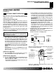
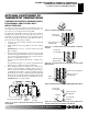
OPTIONAL POSITIONING OF
THERMOSTAT SENSING BULB
(THERMOSTAT-CONTROLLED MODELS ONLY)
FOR MASONRY AND FACTORY-BUILT
METAL FIREPLACE
If your log set cycles to pilot, but the room temperature drops to a
lower than ideal comfort level before the log set comes back on, you
may want to reposition the thermostat sensing bulb.
The thermostat sensing bulb is located on the left side of the base
assembly. This location allows the thermostat to keep the room
temperature at an ideal comfort level for most fireplace applica-
tions. For positioning the thermostat sensing bulb elsewhere, an
adhesive-backed mounting clip is available.
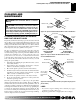
1. Locate the gas valve assembly and thermostat sensing bulb
(see Figure 44).
2. Gently pull thermostat sensing bulb free from the retaining
clamp.
IMPORTANT:
Do not force or bend the thermostat sensing
bulb or capillary.
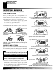
3. The thermostat sensing bulb may be located to the lower right
front side of fireplace. Determine location of sensing bulb, but
do not mount sensing bulb until step 4. If you have a masonry
fireplace, see Figure 46 for location.
If you have a factory-built metal fireplace, see Figure 47 for
location.
If your fireplace has glass doors, position sensing bulb directly
behind door gap on right bottom side (see Figure 48).
4. The mounting clip must be a minimum of 3" from bottom of
fireplace to prevent crimping of capillary. Once you have de-
cided on a location, clean the area thoroughly. Remove the pa-
per backing from the adhesive on back of mounting clip. Press
the clip into the new location so that the thermostat sensing bulb
will be positioned vertically with the capillary at the bottom
(see Figure 49). Slide the thermostat sensing bulb into the clip.
IMPORTANT:
Do not crimp capillary.
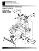
Figure 44 - Location of Gas Valve Assembly and Thermostat
Sensing Bulb
Figure 45 - Adhesive-backed Mounting Clip
Figure 46 - Locating Thermostat Sensing Bulb on Masonry
Fireplace
Figure 47 - Locating Thermostat Sensing Bulb on Factory-built
Metal Fireplace
Adhesive-backed
Mounting Clip
Thermostat
Sensing Bulb
Figure 48- Installing Thermostat Sensing Bulb Behind Glass Doors
Figure 49 - Positioning the Thermostat Sensing Bulb in the
Vertical Position with the Capillary at the Bottom
Adhesive-backed
Mounting Clip
Glass
Door
Thermostat Sensing Bulb
Capillary
Thermostat
Sensing Bulb
Do Not Crimp
Capillary
Adhesive-backed
Mounting Clip
Adhesive-backed
Mounting Clip
Thermostat
Sensing Bulb
OPTIONAL POSITIONING OF THERMOSTAT SENSING BULB
(THERMOSTAT-CONTROLLED MODELS ONLY)
For Masonry and Factory-Built Metal Fireplace
Gas Valve
Assembly
Thermostat Sensing Bulb
Retaining
Clamp