PORTABLE FORCED AIR HEATERS OWNER’S MANUAL Heater Sizes: 35,000 50,000 70,000 100,000 150,000 Btu/Hr Models: NTH35, NTH50, NTH70, NTH100, and NTH150 IMPORTANT: Read and understand this manual before assembling, starting or servicing heater. Improper use of heater can cause serious injury. Keep this manual for future reference.
PORTABLE FORCED AIR HEATERS SAFETY INFORMATION WARNINGS IMPORTANT: Read this Owner’s Manual carefully and completely before trying to assemble, operate, or service this heater. Improper use of this heater can cause serious injury or death from burns, fire, explosion, electrical shock, and carbon monoxide poisoning. DANGER: Carbon monoxide poisoning may lead to death! • Carbon Monoxide Poisoning: Early signs of carbon monoxide poisoning resemble the flu, with headaches, dizziness, and/or nausea.
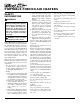
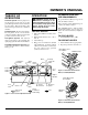
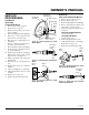
OWNER’S MANUAL PRODUCT IDENTIFICATION Hot Air Outlet UNPACKING 1. 2. 3. Handle Upper Shell Fan Guard Lower Shell Air Filter End Cover Fuel Tank Fuel Cap Side Cover ON/OFF Switch Flame-Out Control Reset Button FUELS WARNING: Use only kerosene or No. 1 fuel oil to avoid risk of fire or explosion. Never use gasoline, naphtha, paint thinners, alcohol or other highly flammable fuels. Do not use heavy fuels such as No. 2 fuel oil or No. 2 Diesel.
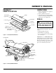
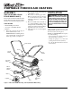
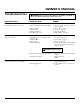
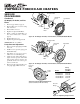
PORTABLE FORCED AIR HEATERS ASSEMBLY 2. (FOR 100,000 AND 150,000 BTU/HR MODELS ONLY) 3. These models are furnished with wheels and handles. Wheels, handles, and the mounting hardware are found in the shipping carton. 4. Tools Needed • Medium Phillips Screwdriver • 3/8" Open or Adjustable Wrench • Hammer 1. Slide axle through wheel support frame. Install wheels on axle. IMPORTANT: When installing wheels, point extended hub of wheels toward wheel support frame (see Figure 3). 5.
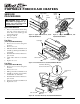
OWNER’S MANUAL THEORY OF OPERATION WARNING: Review and understand the warnings in the Safety Information Section. They are needed to safely operate this heater. Follow all local codes when using this heater. The Fuel System: The air pump forces air through the air line. The air is then pushed through the burner head nozzle. This air causes fuel to lift from the tank. A fine mist of fuel is sprayed into the combustion chamber. The Air System: The motor turns the fan.
PORTABLE FORCED AIR HEATERS STORING, TRANSPORTING, OR SHIPPING PREVENTATIVE MAINTENANCE SCHEDULE WARNING: Never service heater while it is plugged in, operating, or hot. Severe burns and electrical shock can occur. Note: If shipping, transport companies re- quire fuel tanks to be empty. 1. Drain fuel tank. Note: Some models have drain plug on underside of fuel tank. If so, remove drain plug to drain all fuel. If heater does not have drain plug, drain fuel through fuel cap opening.
OWNER’S MANUAL TROUBLESHOOTING WARNING: Never service heater while it is plugged in, operating, or hot. Severe burns and electrical shock can occur. OBSERVED FAULT POSSIBLE CAUSE REMEDY Heater ignites, but flame-out control shuts off heater after a short period of time. 1. Wrong pump pressure 2. Dirty air output, air intake, and lint filters 1. See Pump Pressure Adjustment, page 10. 2. See Air Output, Air Intake and Lint Filters, page 10. 3. See Fuel Filter, page 8. 4. See Nozzle, page 11. 5.
PORTABLE FORCED AIR HEATERS Upper Shell SERVICE PROCEDURES Upper Shell Fan Guard WARNING: Never service heater while it is plugged in, operating, or hot. Severe burns and electrical shock can occur. Fan Guard Upper Shell Removal 1. 2. 3. Remove screws and lock washers along each side of heater using 5/16" nutdriver. These screws attach upper and lower shells together. Lift upper shell off. Remove fan guard.
OWNER’S MANUAL SERVICE PROCEDURES Combustion Chamber Spark Plug Mounting Nut Burner Strap Continued Spark Plug Spark Plug (35,000 Btu/Hr Model) 1. Remove upper shell (see page 8). 2. Remove fan (see page 13). 3. Remove fuel and air line hoses from nozzle assembly. 4. Remove spark plug wire from spark plug. 5. Remove two screws using 5/16" nutdriver and remove burner strap. 6. Place hex-body of spark plug into vise and tighten. 7. Remove spark plug mounting nut using 11/16" open-end wrench. 8.
PORTABLE FORCED AIR HEATERS Air Intake Filter SERVICE PROCEDURES Filter End Cover Continued Fan Guard Air Output, Air Intake, and Lint Filters 1. 2. 3. 4. 5. 6. 7. Remove upper shell (see page 8). Remove filter end cover screws using 5/16" nut-driver. Remove filter end cover. Replace air output and lint filters. Wash or replace air intake filter (see Preventative Maintenance Schedule, page 6). Replace filter end cover. Replace fan guard and upper shell.
OWNER’S MANUAL SERVICE PROCEDURES Burner Strap Continued Nozzle (35,000 Btu/Hr Model) 1. Remove upper shell (see page 8). 2. Remove fan (see page 13). 3. Remove fuel and air line hoses from nozzle assembly. 4. Turn nozzle assembly 1/4 turn to left and pull toward motor to remove. 5. Place plastic hex-body into vise and lightly tighten. 6. Carefully remove nozzle from the nozzle adapter using 5/8" socket wrench. 7. Blow compressed air thru face of nozzle. This will free any dirt in nozzle area. 8.
PORTABLE FORCED AIR HEATERS Blade Pump Plate SERVICE PROCEDURES Air Intake Filter Continued Filter End Cover Pump Rotor (Procedure if Rotor is Binding) 1. Remove upper shell (see page 8). 2. Remove filter end cover screws using 5/16" nut-driver. 3. Remove filter end cover and air filters. 4. Remove pump plate screws using 5/16" nut-driver. 5. Remove pump plate. 6. Remove rotor, insert, and blades. 7. Check for debris in pump. If debris is found, blow out with compressed air. 8.
OWNER’S MANUAL SERVICE PROCEDURES SPECIFICATIONS Output Rating (Btu/Hr) 35,000 Continued Fuel Use Only Kerosene or No. 1 Fuel Oil Fan Fuel Tank Capacity (U.S. Gal./Liters) 3.0/11.4 5.0/18.9 5.0/18.9 9.0/34 13.5/51.1 Fuel Consumption (Gal. Per Hr./ Liters Per Hr.) .26/1.0 .37/1.40 .49/1.85 .70/2.7 1.1/4.1 Electric Requirements 230 V/50 Hz (Same All Models) Amperage (Normal Run) .8 1.0 1.0 1.2 1.2 Hot Air Output (CFM/CMM) 140/4 205/5.8 225/6.4 425/12 500/14.
PORTABLE FORCED AIR HEATERS ILLUSTRATED PARTS BREAKDOWN 3 1 2 NTH35 35,000 BTU/HR MODEL 4 11-5 11-1 5 11-2 6 11 8 7 9 11-4 15 11-3 13 22 13 18 16 23 17 19 20 24 22 21 21 33 34 39 27 31 41 43 29 26 42 30 37 25 28 12 35 32 36 18-1 18-2 18-18 18-4 18-5 22 18-6 18-3 40 18-8 18-17 18-16 14 10 38 18-7 18-9 18-15 45 46 44 18-10 18-11 18-14 Motor and Pump Assembly 18-12 18-13 14 104976
OWNER’S MANUAL PARTS LIST NTH35 35,000 BTU/HR MODEL KEY NO. 1 2 3 4 5 6 7 8 9 10 11 11-1 11-2 11-3 11-4 11-5 12 13 14 15 16 17 18 18-1 18-2 18-3 18-4 18-5 18-6 18-7 18-8 18-9 18-10 18-11 18-12 18-13 18-14 18-15 18-16 18-17 18-18 This list contains replaceable parts used in your heater. When ordering parts, be sure to provide the correct model and serial numbers (from the model plate), then the part number and description of the desired part.
PORTABLE FORCED AIR HEATERS ILLUSTRATED PARTS BREAKDOWN 3 1 2 NTH50 50,000 BTU/HR MODEL 4 5 10 7 6 14 8 12 12 11 18 15 19 Burner Head Assembly 23 17 24 10-1 20 21 10-2 10-4 10-5 21 11 35 10-3 36 41 43 29 10-7 45 27 31 28 44 32 10-6 30 39 33 38 22 18-19 18-1 37 18-2 34 18-18 18-4 40 18-5 18-6 11 13 9 18-7 18-3 18-8 18-17 18-16 42 18-9 18-15 18-10 18-11 18-14 Motor and Pump Assembly 25 26 16 18-12 18-13 16 104976
OWNER’S MANUAL PARTS LIST NTH50 50,000 BTU/HR MODEL KEY NO.
PORTABLE FORCED AIR HEATERS 3 ILLUSTRATED PARTS BREAKDOWN 1 2 4 NTH70 70,000 BTU/HR MODEL 5 10 7 6 14 8 12 12 11 18 15 Burner Head Assembly 19 23 17 24 10-1 20 21 10-2 10-4 10-5 21 11 35 10-3 36 41 43 29 10-7 45 27 31 28 44 32 10-6 30 39 33 38 22 18-19 37 18-1 34 18-2 18-18 40 18-4 18-5 11 13 18-6 9 18-7 18-3 42 25 26 18-8 18-17 18-16 18-9 18-15 18-10 18-11 18-14 Motor and Pump Assembly 16 18-12 18-13 18 104976
OWNER’S MANUAL PARTS LIST NTH70 70,000 BTU/HR MODEL KEY NO.
PORTABLE FORCED AIR HEATERS ILLUSTRATED PARTS BREAKDOWN 2 1 NTH100 100,000 BTU/HR MODEL 3 4 5 8 12 13 14 7 8-1 9 15 8-2 10 8-4 11 17 8-5 30 31 8-3 20 25 26 8-7 21 28 27 23 24 36 8-6 44 Burner Head Assembly 9 33 34 22 18 19 35 32 37 13-19 38 13-1 13-2 13-3 43 42 9 13-4 29 39 16 40 41 13-5 13-6 6 13-7 13-18 46 47 45 13-8 13-17 13-9 13-16 13-15 13-10 13-14 13-11 13-13 Motor and Pump Assembly 13-12 20 104976
OWNER’S MANUAL PARTS LIST NTH100 100,000 BTU/HR MODEL This list contains replaceable parts used in your heater. When ordering parts, be sure to provide the correct model and serial numbers (from the model plate), then the part number and description of the desired part. KEY NO.
PORTABLE FORCED AIR HEATERS ILLUSTRATED PARTS BREAKDOWN 2 1 3 NTH150 150,000 BTU/HR MODEL 4 5 8 12 13 14 7 9 15 8-1 10 8-2 8-4 11 17 30 8-5 31 43 25 26 8-3 28 8-7 21 20 27 23 9 24 8-8 33 34 36 18 19 44 8-6 22 35 32 37 Burner Head Assembly 13-19 38 29 39 16 13-1 13-2 45 42 13-3 40 13-4 41 13-5 13-6 9 47 48 6 13-7 13-18 46 13-8 13-17 13-9 13-16 13-15 13-10 13-14 13-11 13-13 Motor and Pump Assembly 13-12 22 104976
OWNER’S MANUAL PARTS LIST NTH150 150,000 BTU/HR MODEL This list contains replaceable parts used in your heater. When ordering parts, be sure to provide the correct model and serial numbers (from the model plate), then the part number and description of the desired part. KEY NO.
PORTABLE FORCED AIR HEATERS WHEELS AND HANDLES ACCESSORIES Purchase accessories from your local dealer. 100,000 AND 150,000 BTU/HR MODELS KEY PART NO. NUMBER 1 PART DESCRIPTION HA2203 HA2204 M12345-33 M12342-3 M12831-3 NTC-3C 097896-03 M28526 M51015-01 M16801-2 2 3 4 5 6 7 100,000 150,000 QTY. QTY. Handles Handles Screw, #10-24 x 1 3/4" Wheel Support Frame Wheel Support Frame Hex Nut, #10-24 Wheel Cap Nut Axle Axle 2 — 8 1 — 8 2 2 1 — AIR GAUGE KIT - HA1180 — 2 8 — 1 8 2 2 — 1 For all models.
OWNER’S MANUAL EC CONFORMITY DECLARATION EC CONFORMITY DECLARATION NU-TOOL Group Carcroft Industrial Estate, Adwick-Le-Street Doncoster KN6 7DU, England Manufacturer: DESA International, Inc. 2701 Industrial Drive Bowling Green, KY 42101 U.S.A. Kerosene Portable Forced Air Heaters Model Numbers: NTH35, NTH50, NTH70, NTH100, NTH150 It is declared that these models conform to the Machinery Directive 89/392/EEC, including 91/368/EEC and the Low Voltage Directive 73/23/EEC.
WARRANTY INFORMATION CERTIFICATE OF GENERAL EQUIPMENT - LIMITED ONE YEAR WARRANTY NU-TOOL warrants new Products sold by it to be free from defects in material or workmanship for a period of one year after date of delivery to the first user and subject to the following conditions: NU-TOOL's obligation and liability under this Warranty is expressly limited to repairing or replacing at NU-TOOL's option, any parts which appear to NU-TOOL upon inspection to have been defective in material or workmanship when shi