DIRECT-VENT FIREPLACE OWNER’S OPERATION AND INSTALLATION MANUAL Patent Pending NATURAL GAS Models (V)KC36NE Series PROPANE/LP GAS ModelS (V)KC36PE Series WARNING: If the information in this manual is not followed exactly, a fire or explosion may result causing property damage, personal injury or loss of life. — Do not store or use gasoline or other flammable vapors and liquids in the vicinity of this or any other appliance. — WHAT TO DO IF YOU SMELL GAS • Do not try to light any appliance.
Table of Contents Safety Information................................................ 2 Product Identification............................................ 4 Local Codes......................................................... 4 Product Features.................................................. 5 Pre-Installation Preparation.................................. 5 Location of Termination Cap................................. 8 Venting Installation Instructions............................ 9 Fireplace Installation..
Safety information Continued This fireplace must be installed by a qualified (certified or licensed) service person. It has a sealed gas combustion chamber that uses a coaxial pipe (pipe within a pipe and having the same center) venting system. It brings in fresh air for combustion through the outer pipe and combustion gases are exhausted through the inner pipe. If the glass door assembly and venting pipe are not properly seated, connected and sealed, carbon monoxide leakage (spillage) can occur.
Safety information Product Identification Continued 2. If you smell gas • shut off gas supply • do not try to light any appliance • do not touch any electrical switch; do not use any phone in your building • immediately call your gas supplier from a neighbor’s phone. Follow the gas supplier's instructions • if you cannot reach you gas supplier, call the fire department. 3.
Product Features These are a few facts that can help you understand and enjoy your direct-vent fireplace: • The venting system may be routed to the outside of your home in several ways. It may vent through the roof (vertical) or it may vent to an outside/exterior wall (horizontal). The vent pipe installation is very important to allow for proper operation. You must follow the venting instructions very carefully for either vertical or horizontal applications.
Pre-Installation Preparation Continued • Your fireplace is designed to be used in zero clearance installations. Wall or framing material can be placed directly against any exterior surface on the back, sides or top of your fireplace, except where standoff spacers are integrally attached. If standoff spacers are attached to your fireplace, these spacers can be placed directly against wall or framing material. See framing details on page 7.
Pre-Installation Preparation 1 2 Continued 3 A 4 B Wall 5 C D 6 E 7 F G Top of Louver Opening 36 1/8" 41 1/4" 21" Horizontal Vent 24 1/2" Vertical Vent Figure 4 - Framing Clearances for Installation Against an Exterior Wall D 3/8" 10 B 15" C 5/8" 49 35A3/4" E 133/4" F 41" 1 41 G /4" H 681/2" Ref. Mantel Depth Ref.
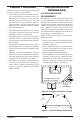
Location of Termination Cap N N D H V L E B C Fixed Closed F B Openable Fixed Closed V Openable V I V G B V B B J V G X G M A V K X V A V TERMINATION CAP X AIR SUPPLY INLET G GAS METER RESTRICTED AREA (TERMINATION PROHIBITED) A = clearance above grade, veranda, porch, deck, or I = clearance to service regulator vent outlet [*72" (182.9 cm) balcony [*12" (30.
Venting Installation Instructions NOTICE: Read these instructions completely before attempting installation. These models are tested and approved for use with DESA (direct-vent) pipe components and terminations. The venting system must terminate on the outside of the structure and can not be attached to a chimney or flue system serving a separate solid fuel or gas burning appliance. A direct-vent appliance must have its own venting system. DO NOT common vent this appliance.
Venting Installation instructions Continued INSTALLATION PLANNING There are two basic types of direct-vent installation: • Horizontal Termination • Vertical Termination Horizontal Termination Installation IMPORTANT: Horizontal square terminations require only inner portion of wall firestop. Horizontal installations using round termination require exterior portion of wall firestop (see Figure 14, page 12). 1.
Venting Installation instructions Apply Mastic to All Four Sides Continued WARNING: Do not recess vent termination into any wall. This will cause a fire hazard. 6. Noncombustible Exterior Wall: Position the horizontal vent cap in the center of the 8 1/2" round hole and attach to the exterior wall with four wood screws provided. Before attaching the vent cap to exterior wall, run a bead of non-hardening mastic (pliable sealant) around the outside edges to make a seal between it and the outside wall.
Venting Installation instructions Continued Minimum Pipe Overlap 11/4" Direct-Vent Pipe Siding Standoff Screws Wall Firestop GROUND FLOOR INSTALLATION Recommended Applications: • Installation using cabinet surrounds • Through the wall using round or square termination (up to 12" horizontal pipe) • NOT FOR CORNER INSTALLATION Adjustable Horizontal Pipe 12" Max.
Venting Installation instructions Continued CORNER INSTALLATION Recommended Applications: • Corner ground floor installation • Ground floor installation where pipe vents horizontally through wall (over 12" horizontal pipe) • Basement installation where one foot clearance from ground to termination is possible Not to Exceed (H) Limits 90° Elbow Square Termination Not to Exceed (H) Limits 90° Elbow Wall Firestop As Required for (V), See Chart for Pipe Section Required Square Termination 12" Min.
Venting Installation instructions Continued HORIZONTAL SYSTEM INSTALLATION USING TWO 90° ELBOWS The following configurations show the minimum vertical rise requirements for a horizontal system using two 90° elbows. 45° Elbow Venting with Two 90° Elbows Horizontal (H1) + Vertical (V) Horizontal (H1) Horizontal (H2) 5' min. 6' min. 7' min. 8' min. 20' max. 2' max. 4' max. 6' max. 8' max. 8' max. 6' max. 12' max. 18' max. 20' max. 20' max.
Venting Installation instructions Continued installation for vertical termination Note: Vertical restrictor must be installed in all vertical installations. 1. Determine the route your vertical venting will take. If ceiling joists, roof rafters or other framing will obstruct the venting system, consider an offset (see Figure 19) to avoid cutting load bearing members.
Venting Installation instructions Continued 5. Place the flashing over the pipe section(s) extending through the roof. Secure the base of the flashing to the roof and framing with roofing nails. Be sure roofing material overlaps the top edge of the flashing as shown in Figure 19, page 15. There must be a 1" clearance from the vent pipe to combustible materials. 6. Continue to add pipe sections until the height of the vent cap meets the minimum building code requirements described in Figure 7 on page 8.
Venting Installation instructions Continued Vertical Venting V = 40' max. Note: Install restrictor into inner collar of fireplace as shown. 45° Elbow 45° Elbow Venting with Two 90° Elbows Vertical (V1) Horizontal (H) 5' min. 6' min. 7' min. 8' min. 6' max. 12' max. 18' max. 20' max. Note: Vertical (V1) + Vertical (V2) = 40' max.
Venting Installation instructions Continued parts list for venting kits and components DESA (5"/8") Pipe & Vent Kits Number Description P58-6 6" Section Double Wall Pipe, Galvanized P58-12 12" Section Double Wall Pipe, Galvanized P58-24 24" Section Double Wall Pipe, Galvanized P58-36 36" Section Double Wall Pipe, Galvanized P58-48 48" Section Double Wall Pipe, Galvanized PA58-712 Adjustable 7"-12" Section Double Wall Pipe, Galvanized E58-45 45° Elbow, Galvanized E58-90 90° Elbow, Galvanized VKG-58 Ground Fl
Fireplace Installation CHECK GAS TYPE Use proper gas type for the fireplace unit you are installing. If you have conflicting gas types, do not install fireplace. See retailer where you purchased the fireplace for proper fireplace according to your gas type or to purchase gas conversion kit (see Accessories, page 35). Installing optional blower accessories NOTICE: If installing blower in an existing fireplace with gas connections, shut off gas supply and disconnect heater from gas supply.
Fireplace Installation Continued CAUTION: Never touch the blower wheel while in operation. 9. Check to make sure that the power cord is completely clear of the blower wheel and that there are no other foreign objects in blower wheel. Turn blower on and check for operation. Turn blower off by turning knob fully counterclockwise before continuing. 10. Peel off the backing paper and stick the supplied wiring diagram decal on the firebox bottom approximately 12" in front of the blower (see Figure 27).
Fireplace Installation Installing Gas Piping to Fireplace Location Continued 7. Check to make sure that the power cord is completely clear of the blower wheel and that there are no other foreign objects in blower wheel. Also double check all wire leads and make sure wire routing is not pinched or in a precarious position. Correct accordingly. 8. Turn on power to duplex outlet if previously turned off per the warning in column 1, page 19. 9. Plug in blower power cord to duplex outlet. 10.
Fireplace Installation Continued CAUTION: Use only new, black iron or steel pipe. Internally-tinned copper tubing may be used in certain areas. Check your local codes. Use pipe of 1/2" diameter or greater to allow proper gas volume to fireplace. If pipe is too small, undue loss of volume will occur. Installation must include an equipment shutoff valve, union and plugged 1/8" NPT tap. Locate NPT tap within reach for test gauge hook up. NPT tap must be upstream from fireplace (see Figure 31).
Fireplace Installation Continued Equipment Shutoff Valve 1/2" NPT Incoming Gas Line Flexible Gas Line Do NOT Kink Red Surface Indicates For Propane/LP Use Only Inlet Pressure Tap Outlet Pressure Tap Note: Wire Connections Not Shown for Clarity Figure 32 - Connecting Flexible Gas Line to Electronic Valve CHECKING GAS CONNECTIONS WARNING: Test all gas piping and connections , internal and external to unit, for leaks after installing or servicing. Correct all leaks at once. 4.
Fireplace Installation Continued Pressure Testing Fireplace Gas Connections 1. Open equipment shutoff valve (see Figure 33, page 23). 2. Open propane/LP supply tank valve for propane/LP fireplace or main gas valve located on or near gas meter for natural gas fireplace. 3. Make sure control knob of fireplace is in the OFF position. 4. Check all joints from equipment shutoff valve to gas valve (see Figure 34 or 35 on page 23). Apply noncorrosive leak detection fluid to all joints. Bubbles forming show a leak.
Fireplace Installation 3. Close glass door, lock door latches, replace screen and close louvers (see Removing Glass Door, steps 5 through 7). Continued 4. Remount the new frame at the hinge with five new screws before closing door. This will ensure seating of the gasket. 5. Close glass door frame. Lock latches by placing the bar under the tab on door and pushing down and back on latch (see Figure 37, page 24). 6. Replace screen/rod assembly by reversing step 1. 7.
Fireplace Installation WALL SWITCH INSTALLATION Continued 7. Remove three screws from deflector shield on the inside top of firebox. Set shield and screws aside. 8. Install rear brick panel first. Rest bottom edge of panel on back edge of burner assembly (see Figure 39). 9. Install left side brick panel by sliding it between the burner assembly and the side of the firebox (see Figure 39). 10. Install the right brick panel using the same method described in step 6 for left brick panel. 11.
Wiring Diagram PILOT IGNITOR LEAD ORANGE BLUE E6 E4 E3 E2 WHITE 120V AC E8 TRANSFORMER 24V AC EV1 SYNETEK CONTROLS INC IS1070B E12 BLACK GROUND EV2 RED GREEN 116238-01E www.desatech.
Operating Fireplace for your safety Read before lighting WARNING: If you do not follow these instructions exactly, a fire or explosion may result causing property damage, personal injury or loss of life. A. This appliance has a pilot which must be lighted by hand. When lighting the pilot, follow these instructions exactly. B. BEFORE LIGHTING smell all around the appliance area for gas. Be sure to smell next to the floor because some gas is heavier than air and will settle on the floor.
OPERATIng fireplace Continued OPTIONAL REMOTE OPERATION Note: The WRC receiver and hand-held remote control kit must be purchased separately (see Accessories, page 35). Follow installation instructions on page 26. 1. Turn equipment shutoff valve to ON position. You can now turn the burner on and off with the hand-held remote control unit. IMPORTANT: Be sure to press the ON/OFF buttons on the hand-held remote control unit for up to 3 seconds to assure proper operation.
Cleaning and Maintenance WARNING: Turn off fireplace and let cool before cleaning. CAUTION: You must keep control areas, burners and circulating air passageways of fireplace clean. Inspect these areas of fireplace before each use. Have fireplace inspected yearly by a qualified service person. Fireplace may need more frequent cleaning due to excessive lint from carpeting, bedding material, pet hair, etc. GLASS DOOR WARNING: Handle glass door panel with care. Do not strike, slam or otherwise abuse glass.
Cleaning and Maintenance Continued venting system Conduct annual inspection of the venting system following these guidelines: 1. Check areas of venting system that are exposed to the weather for corrosion (rust spots or streaks and, in extreme cases, holes). Have these items replaced immediately by a qualified service person. 2. Remove the vent cap and shine a flashlight into the vent. Remove any foreign material. 3. Check for evidence of excessive condensation.
TROUBLESHOOTING Continued OBSERVED PROBLEM POSSIBLE CAUSE Pilot will not stay lit 1. Loose wiring on ignitor wire 1. Check wiring connection. to ignition module and/or Refer to wiring diagram (see poor ground to ignition modWiring Diagram, page 27) ule and/or check ground wire to ignition module 2. Pilot flame too low to sense 2.
TROUBLESHOOTING Continued WARNING: If you smell gas • Shut off gas supply. • Do not try to light any appliance. • Do not touch any electrical switch; do not use any phone in your building. • Immediately call your gas supplier from a neighbor’s phone. Follow the gas supplier’s instructions. • If you cannot reach your gas supplier, call the fire department. OBSERVED PROBLEM POSSIBLE CAUSE REMEDY Gas odor even when control 1. Gas leak. See Warning 1.
Replacement Parts Note: Use only original replacement parts. This will protect your warranty coverage for parts replaced under warranty. Parts Under Warranty Contact authorized retailers of this product. If they can not supply original replacement part(s), call DESA’s Customer Service Department at 1-866-672-6040.
Accessories Perimeter Trim kit Notice: All accessories may not be available for all fireplace models. Purchase these fireplace accessories from your local retailer. If they can not supply these accessories, call DESA at 1-866-672-6040 for information. You can also write to the address listed on the back page of this manual.
Illustrated Parts Breakdown Models KC36NE, VKC36NE, KC36PE and VKC36PE series 21 22 24 6 7 23 8 9 4 11 20 18 12 13 3 19 10 17 1 2 14 16 15 36 5 www.desatech.
PARTS LIST Models KC36NE, VKC36NE, KC36PE and VKC36PE Series This list contains replaceable parts used in your fireplace. When ordering parts, follow the instructions listed under Replacement Parts on page 34 of this manual. KEY NO.
illustrated parts breakdown burner assembly for Models KC36NE, KC36PE, VKC36NE and VKC36PE 12 1 2 7 10 20 15 3 19 18 17 12 13 4 5 9 17 18 21 22 14 23 11 12 6 14 16 8 24 26 30 31 33 25 28 32 27 29 38 www.desatech.
PARTS LIST burner assembly for Models KC36NE, KC36PE, VKC36NE and VKC36PE This list contains replaceable parts used in your fireplace. When ordering parts, follow the instructions listed under Replacement Parts on page 34 of this manual. KEY NO. PART NO.
Warranty Information KEEP THIS WARRANTY Model Serial No. Date Purchased Always specify model and serial numbers when communicating with the factory. We reserve the right to amend these specifications at any time without notice. The only warranty applicable is our standard written warranty. We make no other warranty, expressed or implied.