
OWNER'S Manual FORCED AIR HEATER TB100, TB104, TB106, TB110 85,000 BTU MODELS TB102, TB111, TB114 125,000 BTU TB101, TB105, TB107, TB112 170,000 BTU TB103, TB108, TB113


www.desatech.com
119143-01A4
Air For
Combustion
Air For
Heating
UNPACkINg
1. Remove all packing items applied to
heater for shipment. Keep plastic cover
cap (attached to heater inlet connector and
hose/regulator assembly) for storage.
2. Remove all items from carton.
3. Check all items for shipping damage. If
heater is damaged, promptly inform dealer
where you bought heater.
ASSEMBLy
IMPORTANT: Do not use this product without
leg and foot assembly.
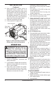
Handle
Attach handle to control box with 2 screws
(long) as shown in Figure 3.
1. Insert leg extensions into outlet end cap
until small hole lines up with larger hole,
visible from inside of outlet end cap (see
Figure 3). Fasten leg extensions with
provided screws (short).
2. Insert plastic foot ends into each leg ex-
tension and set heater to desired angle.
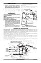
Cool
Air In
(Back)
Motor
Hose/
Regulator
Assembly
Spark Ignitor
Combustion
Chamber
Figure 4 - Cross Section Operational View
Fan
Clean
Heated
Air Out
(Front)
THEORy OF OPERATION
The Fuel System: The hose/regulator assembly attaches to the propane gas supply. For
55/85/125 models, the propane gas moves through the automatic control valve, burn rate
adjustment valve and out the injector. For 170 models, the propane gas moves through the
solenoid valve, burn rate adjustment valve and out the injector.
The Air System: The motor turns the fan. The fan pushes air into and around the combustion
chamber. This air is heated and provides a stream of clean, hot air.
The Ignition System: For 55/85/125 models the high voltage ignitor sends voltage to the spark
ignitor. For 170 models direct spark ignitor sends voltage to the spark ignitor. The spark ignitor
ignites the fuel and air mixture.
The Safety Control System: This system causes the heater to shut down if the flame goes
out. The motor will continue to run, but no heat is produced.
Figure 3 - Handle and Foot Assembly
Solenoid Valve
(170 models only)
Power
Cord
Injector
Thermal
Limit Switch
Small post screws on plastic foot will snap
into holes in leg extensions.
Cord Cleats
Install cord cleats on side of end caps as shown
in Figure 3 with screws provided (short).
Outlet
End Cap
Handle
Leg Extension
Plastic Foot
Small
Post
High Voltage Ignitor (55/85/125
Models) or DSI (170 Models)
Leg Extension
Fastening
Screw (short)
Automatic Control Valve
(55/85/125 models only)
Cord
Cleat
Long screws
Short
Screw