VENTED GAS FIREPLACE OWNER’S OPERATION AND INSTALLATION MANUAL 4 INCH B-VENT DECORATIVE GAS FIREPLACES MODELS: (V) CB36(N,P) (E) WARNING: If the information in this manual is not followed exactly, a fire or explosion may result causing property damage, personal injury, or loss of life. FOR YOUR SAFETY Do not store or use gasoline or other flammable vapors and liquids in the vicinity of this or any other appliance. FOR YOUR SAFETY WHAT TO DO IF YOU SMELL GAS • Do not try to light any appliance.
TABLE OF CONTENTS SAFETY INFORMATION 2 TABLE OF CONTENTS GAS SUPPLY AND PIPING .................................................. 11 SAFETY INFORMATION .......................................................... 2 HEARTH ACCESS AND ASSEMBLY ................................... 14 PRODUCT IDENTIFICATION ................................................... 3 OPERATING FIREPLACE ...................................................... 16 LOCAL CODES ..........................................................
3 SAFETY INFORMATION PRODUCT IDENTIFICATION LOCAL CODES SAFETY INFORMATION PRODUCT IDENTIFICATION Continued 5. This fireplace reaches high temperatures, Keep children and adults away from hot surfaces to avoid burns or clothing ignition. Fireplace will remain hot for a time after shutdown. Allow surfaces to cool before touching. 6. Carefully supervise young children when they are in the room with fireplace. 7. Do not modify this fireplace under any circumstances.
PRODUCT FEATURES PRE-INSTALLATION PREPARATION 4 Location and Space Requirements PRODUCT FEATURES These are a few facts that can help you understand and enjoy your vented decorative fireplace: • Do not install aftermarket vent dampers. Manual or Auto matic vent dampers are not approved for use with this appliance. • The (V)CB36(N,P)(E) series of vented decorative fireplaces may be recessed into an exterior chase, an interior flush wall enclosure or a framed-in corner installation.
5 PRE-INSTALLATION PREPARATION Clearances Framing and Finishing PRE-INSTALATION PREPARATION Continued PACKAGING AND REMOVAL Carton Tray The (V)CB36 vented decorative gas fireplaces are packaged with: - one box containg a 4-log set located on the burner in the firebox. - one bag containing the owner’s manual with installation instructions, operator’s guide, and warranty information. Glass Panel - one bag of glowing ember material. Corner Post - one bag of vermiculite hearth treatments.
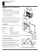
UNIT DIMENSIONS 6 (V)CB36N, (V)CB36P, (V)CB36NE and (V)CB36PE Mantel Clearances UNIT DIMENSIONS (V)CB36 B-Vent Fireplace 14 3/4" (375 mm) TO NAILING FLANGES 7 7/8" (200 mm) TO CENTER OF 4" B-VENT 5 7/8" (150 mm) TO NAILING FLANGE 38" (965 mm) 1 1/4" (32 mm) 2.0" (51 mm) 36 3/4" (934 mm) 35 3/4" (908 mm) 36 1/4" (921 mm) TO NAILING FLANGE 5/8" (16 mm) 36" (914 mm) FACE DIM.
7 INSTALLATION PRECAUTIONS VENTING INSTALLATION INSTALLATION PRECAUTIONS VENTING INSTALLATION NOTICE: Failure to follow these instructions will void the warranty. A 4" B-type venting system must be connected to the appliance for venting to the outside of the building. The following section is provided as a guide to install a standad B-type vent installation.
VENTING INSTALLATION (Cont) CHECKING FOR PROPER VENTING 8 VENTING INSTALLATION Continued Example 1: Shows the minimum allowable system height and lateral offset for a 60° degrees or greater inclination. Code specifies that offsets at 60° degrees or greater are considered horizontal and must follow the 75% percent rule for lateral to total certical system height. Codes also allows only one offset in the total system when at 60° degrees or greater.
9 ELECTRICAL SUPPLY CONNECTION WIRING DIAGRAMS ELECTRICAL SUPPLY CONNECTION CAUTION: Disconnect the electrical power to the supply circuit before attempting to connect or service this appliance. A pre-wired junction box receptacle with strain relief is provided on the right side of the cabinet for hard wiring the unit to a 15 Amp, 120VAC, 60Hz grounded branch circuit.
INSTALLING OPTIONAL CONTROLS Installing Optional Wall Mount Switch - GWMS2 Installing Optional Wireless Hand-Held Remote Control - HRC100 Series 10 INSTALLING OPTIONAL CONTROLS Installing 9-Volt Alkaline Battery in Hand-Held Remote Control Unit INSTALLING OPTIONAL WALL MOUNT SWITCH - GWMS2 1. Connect one terminal of 15 ft. wire from the wall switch to the male connector on the high limit harness. Connect remaining wire terminal to the TH terminal on the valve.
11 INSTALLATING OPTIONAL CONTROLS (Cont.
GAS SUPPLY AND PIPING (Cont) Installing Gas Piping to Fireplace (Cont.) Connecting Fireplace to Gas Supply 12 GAS SUPPLY AND PIPING Continued INSTALLING GAS PIPING TO FIREPLACE (Cont.) CONNECTING FIREPLACE TO GAS SUPPLY Installation Items Needed CSA Design-Certified Equipment Shutoff Valve with 1/8" NPT Tap* Natural - From Gas Meter (5.5" W.C. to 10.5" W.C. Pressure) Approved Flexible Propane/LP Gas Line From External Regulator (11" W.C. to 14" W.C.
13 GAS SUIPPLY AND PIPING (Cont.) Checking Gas Connections GAS SUPPLY AND PIPING Continued CHECKING GAS CONNECTIONS WARNING: Test all gas piping and connections, internal and external to unit, for leaks after installing. or servicing. Correct all leaks at once. Propane/LP Supply Tank Equipment Shutoff Valve WARNING: Never use an open flame to check for a leak.Apply noncorrosive leak detection fluid to all joints. Bubbles forming show a leak. Correct all leaks at once.
HEARTH ACCESS AND ASSEMBLY Removing Lower Louver Access Panel Removing Top Louver Trim Panel Removing/Replacing Glass Door 14 HEARTH ACCESS AND ASSEMBLY WARNING: If fireplace has been running, turn off and let cool before accessing or servicing the unit. Removing Lower Louver Access Panel 1. Use your index fingers to locate the left and right spring latches found just under the top louver then draw them inward to release the pins holding the panel on the side face (see Figure 28). 2.
HEARTH ACCESS AND ASSEMBLY (Cont.) 15 Installing Logs and Glowing Embers HEARTH ACCESS AND ASSEMBLY Continued INSTALLING LOGS AND GLOWING EMBERS WARNING: The glass door must be securely in place before running this fireplace. Do not run this fireplace if glass is missing or broken. A 4 piece ceramic log set comes packed inside the unit firebox. Removal of glass door is necessary to unpack and assemble the logs and add hearth treatments.
OPERATING FIREPLACE - Manual Ignition System 16 For Your Safety Read Before Lighting Lighting Instructions To Turn Off Gas To Appliance Manual Lighting Procedure OPERATING FIREPLACE Manual Ignition System FOR YOUR SAFETY READ BEFORE LIGHTING WARNING: If you do not follow these instructions exactly, a fire or explosion may result causing property, damage, personal injury or loss of life. • If gas control knob does not pop up when released, stop and immediately call your service technician or gas suppier.
17 OPERATING FIREPLACE - Electronic Ignition System For Your Safety Read Before Lighting Lighting Instructions To Turn Off Gas To Appliance Optional Wireless Remote Operation OPERATING FIREPLACE Electronic Ignition System FOR YOUR SAFETY READ BEFORE LIGHTING NOTICE: During initial operation of a new heater, the burning of residues from the manufacturing process of the firebox and logs will produce a paper-burning smell and orange flames.
OPERATING FIREPLACE Optional Hand-Held Remote Operation Operating Optional GWMS2 Wall Mounted Switch 18 OPERATING FIREPLACE Continued OPTIONAL HAND-HELD REMOTE OPERATION Note: All remote control accessories must be purchased separately (see Accessories, page 33). Follow instructions included with the remote control. Indicator Light NOTICE:You must light the pilot before using the handheld remote control unit. See Lighting Instructions.
19 INSPECTING BURNERS Pilot Assembly Burner Flame Pattern INSPECTING BURNERS Check pilot flame pattern and burner flame patterns often. PILOT ASSEMBLY The pilot assembly is factory preset for the proper flame height Alterations may have occurred during shipping and handling. Call a qualified service person to readjust the pilot if necessary. The position and pattern of the pilot flames in relation to the sensing devices should be as shown in Figures 38 and 39 respectively.
CLEANING AND MAINTENANCE Gass Door Pilot and Burners Logs Venting System 20 CLEANING AND MAINTENANCE CAUTION: Do not vacumm if pieces are hot. WARNING: Turn off fireplace and let cool before cleaning. CAUTION: You must keep control areas, burners, and circulating air passages of fireplace clean. Inspect these areas of fireplace before each use. Have fireplace inspected yearly by a qualified service person.
21 TROUBLESHOOTING Manual Ignition System TROUBLESHOOTING Manual Ignition System Note: For additional help, visit DESA’s technical service web site at www. desatech.com Note: All troubleshooting items are listed in order of operation. WARNING: Turn off heater and let cool before servicing. Only a qualified service person should service and repair heater. CAUTION Never use a wire, needle, or similar object to clean pilot. This can damage pilot unit.
TROUBLESHOOTING Manual Ignition System (Cont.) 22 TROUBLESHOOTING Manual Ignition System (Continued) OBSERVED PROBLEM POSSIBLE CAUSE REMEDY Burner does not light after pilot is lit or cycles during operation. 1. Burner orifice clogged 1. Clean burner (see Cleaning and Maintenance, page 20) or replace burner orifice 2. Contact local propane/LP or natural gas company 3. Reconnect leads 2. Inlet gas pressure is too low 3. Thermopile leads disconnected or improperly connected 4. Thermopile is defective 5.
23 TROUBLESHOOTING Manual Ignition System (Cont.) TROUBLESHOOTING Manual Ignition System (Continued) WARNING: If you smell gas Shut off gas supply. Do not try to light any appliance. Do not touch any electrical switch; do not use any phone in your building. Immediately call your gas supplier from a neighbor’s phone. Follow the gas supplier’s instructions • If you cannot reach your gas supplier, call the fire department.
TROUBLESHOOTING Electronic Ignition System 24 TROUBLESHOOTING Electronic Ignition System Note: For additional help, visit DESA’s technical service web site at www. desatech.com Note: All troubleshooting items are listed in order of operation. WARNING: Turn off heater and let cool before servicing. Only a qualified service person should service and repair heater. CAUTION Never use a wire, needle, or similar object to clean pilot. This can damage pilot unit.
25 TROUBLESHOOTING Electronic Ignition System (Cont.) TROUBLESHOOTING Electronic Ignition System (Continued) WARNING: If you smell gas Shut off gas supply. Do not try to light any appliance. Do not touch any electrical switch; do not use any phone in your building. Immediately call your gas supplier from a neighbor’s phone. Follow the gas supplier’s instructions • If you cannot reach your gas supplier, call the fire department.
REPLACEMENT PARTS SPECIFICATIONS SERVICE HINTS TECHNICAL SERVICE 26 REPLACEMENT PARTS SERVICE HINTS Note: Use only original replacement parts. This will protect your warranty coverage for parts replaced under warranty. When Gas Pressure Is Too Low • pilot will not stay lit PARTS UNDER WARRANTY • burners will have delayed ignition Contact authorized retailers of this product.
27 ILLUSTRATED PARTS BREAKDOWN Models (V)CB36N, (V)CB36P, (V)CB36NE, (V)CB36PE ILLUSTRATED PARTS BREAKDOWN FIREPLACE ASSEMBLY FOR MODELS (V)CB36N, (V)CB36P, (V)CB36NE, (V)CB36PE 10 9 5 6 7 26 27 11 13 18 16 15 26 19 8 4 23 26 22 17 3 2 24 12 20 14 21 25 1-4 12 1-3 1-2 1-1 www.desatech.
PARTS LIST Models (V)CB36N, (V)CB36P, (V)CB36NE, (V)CB36PE PARTS LIST FIREPLACE ASSEMBLY FOR MODELS (V)CB36N, (V)CB36P, (V)CB36NE, (V)CB36PE This list contains replaceable parts used in your fireplace. When ordering parts, follow the instructions listed under Replacement Parts on page 26 of this manual. KEY (V)CB36N NO.
29 ILLUSTRATED PARTS BREAKDOWN Models (V)CB36N, (V)CB36P ILLUSTRATED PARTS BREAKDOWN BURNER ASSEMBLY FOR MODELS (V)CB36N, (V)CB36P 2 19 3 4 7 15 14 1 13 9 6 5 11 17 10 8 18 www.desatech.
PARTS LIST Models (V)CB36N, (V)CB36P PARTS LIST BURNER ASSEMBLY FOR MODELS (V)CB36N, (V)CB36P This list contains replaceable parts used in your fireplace. When ordering parts, follow the instructions listed under Replacement Parts on page 26 of this manual. KEY NO.
31 ILLUSTRATED PARTS BREAKDOWN Models (V)CB36NE, (V)CB36PE ILLUSTRATED PARTS BREAKDOWN BURNER ASSEMBLY FOR MODELS (V)CB36NE, (V)CB36PE 8 29 7 9 10 26 13 19 22 24 21 1 6 5 28 2 20 3 4 23 16 12 11 14 27 25 18 17 15 28 www.desatech.
PARTS LIST Models (V)CB36NE, (V)CB36PE PARTS LIST BURNER ASSEMBLY FOR MODELS (V)CB36NE, (V)CB36PE This list contains replaceable parts used in your fireplace. When ordering parts, follow the instructions listed under Replacement Parts on page 26 of this manual. KEY NO.
33 ACCESSORIES ACCESSORIES NOTE: All accessories may not be available for all fireplace models. Purchase these fireplace accessories from your local retailer. If they can not supply these accessories, call DESA’s Sales Department at 1-866-672-6040, for information.
OWNER’S REGISTRATION FORM In order to provide better customer service for this and future purchases, we recommend that you register your product with us. You can resister online at www.desatech.com. If access to our website is not available to you, please complete the Owner’s Registration Form and mail to the address on the back of this owner’s manual. Please provide the following product information: Brand: _____________________________________ (Comfort Glow, Vanguard, etc.
TAPE Postage Required 2701 Industrial Drive P.O.
36 NOTES 117437-01 www.desatech.
37 NOTES www.desatech.
WARRANTY INFORMATION KEEP THIS WARRANTY Model Serial No. Date Purchased Always specify model and serial numbers when communicating with the factory. We reserve the right to amend these specifications at any time without notice. The only warranty applicable is our standard written warranty. We make no other warranty, expressed or implied.