DIRECT-VENT FIREPLACE OWNER’S OPERATION AND INSTALLATION MANUAL DEDICATED REAR AND TOP VENT FIREPLACES MODELS: (V) CD36R(N,P) (E) WARNING: If the information in this manual is not followed exactly, a fire or explosion may result causing property damage, personal injury, or loss of life. FOR YOUR SAFETY Do not store or use gasoline or other flammable vapors and liquids in the vicinity of this or any other appliance. FOR YOUR SAFETY WHAT TO DO IF YOU SMELL GAS • Do not try to light any appliance.
TABLE OF CONTENTS SAFETY INFORMATION TABLE OF CONTENTS GAS SUPPLY AND PIPING .................................................. 21 SAFETY INFORMATION .......................................................... 2 HEARTH ACCESS AND ASSEMBLY ................................... 24 PRODUCT IDENTIFICATION ................................................... 3 OPERATING FIREPLACE ...................................................... 25 LOCAL CODES ..........................................................
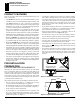
SAFETY INFORMATION PRODUCT IDENTIFICATION LOCAL CODES SAFETY INFORMATION PRODUCT IDENTIFICATION Continued 5. This fireplace reaches high temperatures, Keep children and adults away from hot surfaces to avoid burns or clothing ignition. Fireplace will remain hot for a time after shutdown. Allow surfaces to cool before touching. 6. Carefully supervise young children when they are in the room with fireplace. 7. Do not modify this fireplace under any circumstances.
PRODUCT FEATURES PRE-INSTALLATION PREPARATION Location and Space Requirements PRODUCT FEATURES These are a few facts that can help you understand and enjoy your direct-vent fireplace: • The CD36R dedicated rear vent is best suited for flush or corner installations when vented horizontally through an exterior wall.
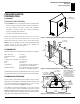
PRE-INSTALLATION PREPARATION Clearances Framing and Finishing 5 PRE-INSTALATION PREPARATION Continued FIBERBOARD COLLAR PROTECTOR PACKAGING AND REMOVAL The (V)CD36R/T direct vent gas fireplace heater is packaged with: - one box containg a 4-log set located on the burner in the firebox. - one bag containing the owner’s manual with installation instructions, operator’s guide, and warranty information. - one bag of glowing ember material. - one bag of vermiculite hearth treatments.
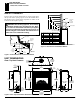
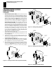
UNIT DIMENSIONS REAR / TOP VENT COMMON CD36R, CD36T, VCD36R and VCD36T MANTEL CLEARANCES 1 Figure 8 shows projected mantel depths at various heights above the top of the louver opening. Figure 7 shows the minimum allowable distances from various mantel components in relation to the both sides of the fireplace opening. WARNING: When finishing appliance, do not overlap combustible materials onto the black front face.
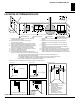
LOCATION OF TERMINATION CAP 7 LOCATION OF TERMINATION CAP N N D H V L E B C Fixed Closed F B Openable Fixed Closed V Openable V I V G B V B B J V G X G M A V K X V A V TERMINATION CAP A = clearance above grade, veranda, porch, deck, or balcony [*12 inches (30.5mc) minimum] B = clearance to window or door that may be opened [12 inches (30.5cm) minimum] C = clearance to permanently closed window [minimum 12 inches (30.
VENTING INSTALLATION INSTRUCTIONS Installation Planning VENTING INSTALLATION INSTRUCTIONS NOTICE: Read these instructions completely before attempting installation. These models are tested and approved for use with DESA (directvent) pipe components and terminations. The venting system must terminate on the outside of the structure and can not be attached to a chimney or flue system servicing a solid fuel or gas burning appliance. A direct-vent appliance must have its own venting system.
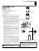
VENTING INSTALLATION INSTRUCTIONS Installation Planning (Cont.) 9 VENTING INSTALLATION INSTRUCTIONS Continued INSTALLATION PLANNING There are two basic types of direct-vent installations: Female Locking Lugs • Horizontal Termination • Vertical Termination Horizontal Termination Installation IMPORTANT: Horizontal square terminations require only inner portion of wall firestop. Horizontal installation using round termination require exterior portion of wall firestop (see Figure 18, page 11). 1. 2.
VENTING INSTALLATION INSTRUCTIONS Installation Planning (Cont.) VENTING INSTALLATION INSTRUCTIONS INNER WALL FIRESTOP Continued 6. Noncombustible Exterior Wall: Position the horizontal vent cap in the center of the 8 ½” round hole and attach to the exterior wall with four wood screws provided. Before attaching the vent cap to exterior wall, run a bead of non-hardening mastic (pliable sealant) around the outside edges to make a seal between it and the outside wall.
VENTING INSTALLATION INSTRUCTIONS Installation Planning (Cont.) VENTING INSTALLATION INSTRUCTIONS 90° Elbow 11 Exterior Portion of Wall Firestop (Round Termination Only) Wall Firestop Continued Horizontal Termination Configuration Figures 19 through 25 show different configurations and alternatives for venting with horizontal terminations. Each figure includes a chart with critical minimum and maximum dimensions which MUST be met.
VENTING INSTALLATION INSTRUCTIONS Installation Planning (Cont.) VENTING INSTALLATION INSTRUCTIONS Continued Required Vertical (V) 45 ½” 57 ¼” Min. 69 ¼” Min. 81 ½” Min. 94” Min. 106” Min. 159” Min.
VENTING INSTALLATION INSTRUCTIONS Installation Planning (Cont.) HORIZONTAL SYSTEM INSTALLATION USING TWO 90° ELBOWS The following configurations show the minimum vertical rise requirements for a horizontal system using two 90° elbows. Venting with Two 90° Elbows Vertical (V) Horizontal (H1) + Horizontal (H2) 8' min. 9' min. 10' min. 12' min. 14' min. 9' max. 11' max. 13' max. 17' max. 20' max.
VENTING INSTALLATION INSTRUCTIONS Installation for Vertical Terminations VENTING INSTALLATION INSTRUCTIONS Continued 2. Assemble the desired lengths of pipe and elbows necessary to reach from the fireplace flue up through the firestop. Be sure all pipe and elbow connections are fully twist-locked (see Figure 11, page 9). 3. Cut a hole in the roof using the locating hole as a center point. (Cover any exposed open vent pipes before cutting hole in roof.
VENTING INSTALLATION INSTRUCTIONS Installation for Vertical Termination (Cont.) VENTING INSTALLATION INSTRUCTIONS Note: Install restrictor ring into inner pipe section prior to attaching vent termination cap. Continued Vertical Termination Configurations Figures 28 through 31 show four different configurations for vertical termination.
VENTING INSTALLATION INSTRUCTIONS Installation for Vertical Terminations Cont.) Parts Lists for Venting Kits Components VENTING INSTALLATION INSTRUCTIONS Continued PARTS LISTS FOR VENTING KITS AND COMPONENTS DESA (5/8”) Pipe & Vent Kits Number P58-6 P58-12 P58-24 P58-36 P58-48 PA58-712 Note: Install restrictor ring into inner pipe section prior to attaching vent termination cap. Vertical Venting V = 40' max.
ELECTRICAL SUPPLY CONNECTION OPTIONAL BLOWER INSTALLATION Models BK and BKT 17 ELECTRICAL SUPPLY CONNECTION J-BOX COVER w/ STRAIN RELIEF J-BOX COVER CAUTION: Disconnect the electrical power to the supply circuit before attempting to connect or service this appliance. WARNING: This appliance, when installed must be electrically grounded in accordance with local code or in the absence of local code, with the current National Electric Code, ANSI/NFPA 70, or the Canadian Electric Code, CSA C22.1.
OPTIONAL BLOWER INSTALLATION (Cont.) Models BK and BKT OPTIONAL BLOWER INSTALLATION Continued 4. Be certain that all wire terminals are securely attached to terminals on blower motor and that the screw retaining the green ground wire is tight. 5. Mount speed control box by placing the plastic control shaft through the opening in switch bracket (see Figure 34) or the igniton module bracket (see Figure 35). 6.
OPTIONAL BLOWER INSTALLATION (Cont.) 19 Models BK and BKT) WiIRING DIAGRAMS Blower Wiring Diagram Millivolt Ignition Wiring Diagram Electronic Ignition Wiring Diagram OPTIONAL BLOWER INSTALLATION Continued 4. Be certain that all wire terminals are securely attached to terminals on blower motor and thermal switch, and that the screw for the thermodisc bracket and green ground wire is tight. 5.
INSTALLING OPTIONAL CONTROLS Installing Optional Wall Mount Switch - GWMS2 Installing Optional Wireless Hand-Held Remote Control - GHRC and GHRCT Series INSTALLING OPTIONAL CONTROLS INSTALLING OPTIONAL WALL MOUNT SWITCH - GWMS2 Installing 9-Volt Alkaline Battery in Hand-Held Remote Control Unit 1. Remove battery cover on back of remote control unit. 1. 2. Attach terminal wires to a 9-volt alkaline battery (not included). Place battery into the battery housing. (see Figure 44). 3.
INSTALLATING OPTIONAL CONTROLS (Cont.) Installing Optional Wireless Remote Control - Model WRC HIGH ALTITUDE INSTALLATION GAS SUPPLY AND PIPING 21 Check Gas Type Installing Gas Piping to Fireplace INSTALLING OPTIONAL CONTROLS Continued INSTALLING OPTIONAL WIRELESS REMOTE CONTROL - MODEL WRC (Electronic Ignition) Installing and Activating the Remote Receiver 1. Open bottom louver and locate the plug receptacle. The plug receptacle is located either on the right or left side of cabinet. 2.
GAS SUPPLY AND PIPING (Cont) Installing Gas Piping to Fireplace (Cont.) Connecting Fireplace to Gas Supply GAS SUPPLY AND PIPING Continued INSTALLING GAS PIPING TO FIREPLACE (Cont.) CONNECTING FIREPLACE TO GAS SUPPLY Installation Items Needed CSA Design-Certified Equipment Shutoff Valve with 1/8" NPT Tap* Natural - From Gas Meter (5.5" W.C. to 10.5" W.C. Pressure) Approved Flexible Propane/LP Gas Line From External Regulator (11" W.C. to 14" W.C.
GAS SUIPPLY AND PIPING (Cont.) Checking Gas Connections 23 GAS SUPPLY AND PIPING Continued CHECKING GAS CONNECTIONS WARNING: Test all gas piping and connections, internal and external to unit, for leaks after installing. or servicing. Correct all leaks at once. Propane/LP Supply Tank WARNING: Never use an open flame to check for a leak.Apply noncorrosive leak detection fluid to all joints. Bubbles forming show a leak. Correct all leaks at once.
HEARTH ACCESS AND ASSEMBLY Removing Lower Louver Access Panel Removing Top Louver Trim Panel Removing/Replacing Glass Door HEARTH ACCESS AND ASSEMBLY Removing Lower Louver Access Panel 1. Grasp the lower louver panel and pull up until the hanger brackets release from the door pins (see Figure 53). 2. Swing the louver panel out until it clears the fireplace opening. 3. Pull the entire panel out until the bottom tabs are free of the slot openings in the lower face frame.
HEARTH ACCESS AND ASSEMBLY (Cont.) Installing Logs and Glowing Embers OPERATING FIREPLACE - Manual Ignition System 25 For Your Safety Read Before Lighting HEARTH ACCESS AND ASSEMBLY Continued INSTALLING LOGS AND GLOWING EMBERS A 4 piece ceramic log set comes packed inside the unit firebox. Removal of glass door is necessary to unpack and assemble the logs and add hearth treatments. Follow steps under Removing/Replacing Glass Door, page 24 to access the logs and burner.
OPERATING FIREPLACE - Manual Ignition System For Your Safety Read Before Lighting (cont.) Lighting Instructions To Turn Off Gas To Appliance Manual Lighting Procedure Operating Hand-Held Remote Operation OPERATING FIREPLACE Manual Ignition System (Continued) • If you cannot reach your gas supplier, call the fire department. C. Use only your hand to push in or turn the gas control knob. Never use tools.
OPERATING FIREPLACE - Electronic Ignition System 27 For Your Safety Read Before Lighting Lighting Instructions To Turn Off Gas To Appliance Optional Wireless Remote Operation OPERATING FIREPLACE Electronic Ignition System FOR YOUR SAFETY READ BEFORE LIGHTING NOTICE: During initial operation of a new heater, the burning of residues from the manufacturing process of the firebox and logs will produce a paper-burning smell and orange flames.
OPERATING FIREPLACE Optional Hand-Held Remote Operation (Cont.) OPERATING FIREPLACE Continued Auto (Thermostat) Mode IMPORTANT: Do not leave the selector switch in the REMOTE or ON position when the pilot is not lit. This will drain the battery. 2. 3. Blower Control Knob (Optional Accessory) HI T F ON OFF REMOTE LO OF PILO Selector Switch in Remote Position ON ON OFF Variable Control Knob 1. 4. Press the POWER and LOCK buttons together to turn on the hand-held remote control.
OPERATING FIREPLACE Operating Optional GWMT1 Wall Mounted Thermostat Operating Optional Blower Accessory 29 INSPECTING BURNERS Pilot Assembly Burner Flame Pattern OPERATING FIREPLACE Continued OPERATING OPTIONAL GWMT1 WALL MOUNTED THERMOSTAT WARNING: Do not connect the thermostat to a 120 VAC power source. Damage or injury may occur. The position and pattern of the pilot flames in relation to the sensing devices should be as shown in Figures 64 and 65 respectively.
CLEANING AND MAINTENANCE Gass Door Pilot and Burners Logs Venting System CLEANING AND MAINTENANCE CAUTION: Do not vacumm if pieces are hot. WARNING: Turn off fireplace and let cool before cleaning. CAUTION: You must keep control areas, burners, and circulating air passages of fireplace clean. Inspect these areas of fireplace before each use. Have fireplace inspected yearly by a qualified service person.
TROUBLESHOOTING Manual Ignition System 31 TROUBLESHOOTING Manual Ignition System Note: For additional help, visit DESA’s technical service web site at www. desatech.com Note: All troubleshooting items are listed in order of operation. WARNING: Turn off heater and let cool before servicing. Only a qualified service person should service and repair heater. CAUTION Never use a wire, needle, or similar object to clean pilot. This can damage pilot unit.
TROUBLESHOOTING Manual Ignition System (Cont.) TROUBLESHOOTING Manual Ignition System (Continued) OBSERVED PROBLEM POSSIBLE CAUSE REMEDY Burner does not light after pilot is lit 1. Burner orifice clogged 1. Clean burner (see Cleaning and Maintenance, page 30) or replace burner orifice 2. Contact local propane/LP or natural gas company 3. Reconnect leads 2. Inlet gas pressure is too low 3. Thermopile leads disconnected or improperly connected 4.
TROUBLESHOOTING Manual Ignition System (Cont.) 33 TROUBLESHOOTING Manual Ignition System (Continued) WARNING: If you smell gas Shut off gas supply. Do not try to light any appliance. Do not touch any electrical switch; do not use any phone in your building. Immediately call your gas supplier from a neighbor’s phone. Follow the gas supplier’s instructions • If you cannot reach your gas supplier, call the fire department.
TROUBLESHOOTING Electronic Ignition System TROUBLESHOOTING Electronic Ignition System Note: For additional help, visit DESA’s technical service web site at www. desatech.com Note: All troubleshooting items are listed in order of operation. WARNING: Turn off heater and let cool before servicing. Only a qualified service person should service and repair heater. CAUTION Never use a wire, needle, or similar object to clean pilot. This can damage pilot unit.
TROUBLESHOOTING Electronic Ignition System (Cont.) 35 TROUBLESHOOTING Electronic Ignition System (Continued) WARNING: If you smell gas Shut off gas supply. Do not try to light any appliance. Do not touch any electrical switch; do not use any phone in your building. Immediately call your gas supplier from a neighbor’s phone. Follow the gas supplier’s instructions • If you cannot reach your gas supplier, call the fire department.
REPLACEMENT PARTS SPECIFICATIONS SERVICE HINTS TECHNICAL SERVICE REPLACEMENT PARTS SERVICE HINTS Note: Use only original replacement parts. This will protect your warranty coverage for parts replaced under warranty. When Gas Pressure Is Too Low • pilot will not stay lit PARTS UNDER WARRANTY • burners will have delayed ignition Contact authorized retailers of this product.
ILLUSTRATED PARTS BREAKDOWN 37 Models (V)CD36RN, (V)CD36RP, (V)CD36TN, (V)CD36TP ILLUSTRATED PARTS BREAKDOWN FIREPLACE ASSEMBLY FOR MODELS (V)CD36RN, (V)CD36RP, (V)CD36TN, (V)CD36TP 1-4 6 1-3 1-2 7 4 12 1-1 11 5 18 14 10 15 13 3 16 17 2 9 19 8 116035-01B www.desatech.
PARTS LIST Models (V)CD36RN, (V)CD36RP, (V)CD36TN, (V)CD36TP PARTS LIST FIREPLACE ASSEMBLY FOR MODELS (V)CD36RN, (V)CD36TN, (V)CD36RP, (V)CD36TP This list contains replaceable parts used in your fireplace. When ordering parts, follow the instructions listed under Replacement Parts on page 36 of this manual. KEY (V)CD36RN (V)CD36TN NO.
ILLUSTRATED PARTS BREAKDOWN Models (V)CD36RN, (V)CD36RP, (V)CD36TN, (V)CD36TP ILLUSTRATED PARTS BREAKDOWN BURNER ASSEMBLY FOR MODELS (V)CD36RN, (V)CD36RP, (V)CD36TN, (V)CD36TP 3 20 4 5 8 16 2 15 1 14 10 7 6 12 18 116035-01B 11 9 19 17 www.desatech.
PARTS LIST Models (V)CD36RN, (V)CD36RP, (V)CD36TN, (V)CD36TP PARTS LIST BURNER ASSEMBLY FOR MODELS (V)CD36RN, (V)CD36TN, (V)CD36RP, (V)CD36TP This list contains replaceable parts used in your fireplace. When ordering parts, follow the instructions listed under Replacement Parts on page 36 of this manual. KEY (V)CD36RN (V)CD36RP NO.
ILLUSTRATED PARTS BREAKDOWN Models (V)CD36RNE, (V)CD36RPE, (V)CD36TNE, (V)CD36TPE ILLUSTRATED PARTS BREAKDOWN BURNER ASSEMBLY FOR MODELS (V)CD36RNE, (V)CD36RPE, (V)CD36TNE, (V)CD36TPE 9 30 8 5 10 11 27 14 23 20 25 22 1 7 6 29 21 2 3 4 24 17 13 12 15 28 116035-01B 26 18 16 29 www.desatech.
PARTS LIST Models (V)CD36RNE, (V)CD36RPE, (V)CD36TNE, (V)CD36TPE PARTS LIST BURNER ASSEMBLY FOR MODELS (V)CD36RNE, (V)CD36TNE, (V)CD36RPE, (V)CD36TPE This list contains replaceable parts used in your fireplace. When ordering parts, follow the instructions listed under Replacement Parts on page 36 of this manual. KEY (V)CD36RNE (V)CD36RPE NO.
ACCESSORIES 43 ACCESSORIES NOTE: All accessories may not be available for all fireplace models. Purchase these fireplace accessories from your local retailer. If they can not supply these accessories, call DESA’s Sales Department at 1-866-672-6040, for information.
NOTES www.desatech.
OWNER’S REGISTRATION FORM In order to provide better customer service for this and future purchases, we recommend that you register your product with us. You can resister online at www.desatech.com. If access to our website is not available to you, please complete the Owner’s Registration Form and mail to the address on the back of this owner’s manual. Please provide the following product information: Brand: _____________________________________ (Comfort Glow, Vanguard, etc.
TAPE Postage Required 2701 Industrial Drive P.O.
WARRANTY INFORMATION KEEP THIS WARRANTY Model Serial No. Date Purchased Always specify model and serial numbers when communicating with the factory. We reserve the right to amend these specifications at any time without notice. The only warranty applicable is our standard written warranty. We make no other warranty, expressed or implied.