DIRECT-VENT FIREPLACE OWNER’S OPERATION AND INSTALLATION MANUAL NATURAL GAS Models (V)CD36RN, (V)CD36RNE NATURAL GAS Models (V)CD36TN, (V)CD36TNE, PROPANE/LP GAS ModelS (V)CD36RP, (V)CD36RPE PROPANE/LP GAS Models (V)CD36TP, (V)CD36TPE WARNING: If the information in this manual is not followed exactly, a fire or explosion may result causing property damage, personal injury or loss of life.
WARNING: Improper installation, adjustment, alteration, service or maintenance can cause injury or property damage. Refer to this manual for correct installation and operational procedures. For assistance or additional information consult a qualified installer, service agency or the gas supplier. This appliance may be installed in an aftermarket,* permanently located, manufactured (mobile) home, where not prohibited by local codes.
Safety Information WARNING: This product contains and/or generates chemicals known to the State of California to cause cancer or birth defects or other reproductive harm. IMPORTANT: Read this owner’s manual carefully and completely before trying to assemble, operate or service this fireplace. Improper use of this fireplace can cause serious injury or death from burns, fire, explosion, electrical shock and carbon monoxide poisoning.
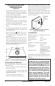
Safety information Continued Carefully supervise young children when they are in the room with fireplace. Keep the area around your fireplace clear of combustible materials, gasoline and other flammable vapor or liquids. Do not run fireplace where these are used or stored. 1. For propane/LP fireplace, do not place propane/LP supply tank(s) inside any structure. Locate propane/LP supply tank(s) outdoors. To prevent performance problems, do not use propane/LP fuel tank of less than 100 lbs. capacity. 2.
Local Codes Install and use fireplace with care. Follow all local codes. In the absence to local codes, use the current National Fuel Gas Code ANSI Z223.1/NFPA 54* (USA) or the current CSA-B149.1 Installation Code (Canada). *Available from: American National Standards Institute, Inc. 1430 Broadway New York, NY 10018 National Fire Protection Association, Inc.
Pre-Installation Preparation Continued • If you plan on installing a television or entertainment center recessed above your fireplace, it is recommended that you maintain a minimum 18" above top of louver opening. • When locating termination cap, it is important to observe the minimum clearances shown in Figure 7, page 8. • If recessing into a wall, you can avoid extra framing by positioning your fireplace against an already existing framing member. • Do not recess termination cap into a wall or siding.
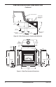
Pre-Installation Preparation Continued framing and finishing Figure 5 shows typical framing of this fireplace. Figure 6 shows framing for corner installation. All minimum clearances must be met. For overall unit dimensions, framing allowances and vent collar locations, see Unit Dimensions, Figure 9, page 8. For available accessories for this fireplace, see Accessories on page 45. If you are using a separate combustible mantel piece, refer to Figure 7 and Figure 8, page 8 for proper height and clearances.
Pre-Installation Preparation Continued Outer Surround Combustible Material May Be Used 1 1/2" (38 mm) SAFE ZONE 6" (152 mm) 5 1/2" (140 mm) 33° 3 3/4" (95 mm) To Fireplace Opening Perpendicular Side Wall 12" (305 mm) Figure 8 - Side Clearances for Combustible Materials 14 3/4" (375 mm) TO NAILING FLANGES 7 5/8" (194 mm) TO CENTER OF 8" TOP VENT 4" (102 mm) TO NAILING FLANGE 38" (965 mm) 2" (51 mm) 2" (51 mm) 36 1/4" (921 mm) TO NAILING FLANGE 36" (914 mm) FACE DIM.
Location of Termination Cap N N D H V L E B C Fixed Closed F B Openable Fixed Closed V Openable V I V G B V B B J X V G G M A V K X V A G GAS METER RESTRICTED AREA V TERMINATION CAP X AIR SUPPLY INLET (TERMINATION PROHIBITED) A = clearance above grade, veranda, porch, deck, or balcony I = clearance to service regulator vent outlet [*72 inches (182.9cm) [*12 inches (30.
Venting Installation Instructions NOTICE: Read these instructions completely before attempting installation. These models are tested and approved for use with DESA (direct-vent) pipe components and terminations. The venting system must terminate on the outside of the structure and can not be attached to a chimney or flue system serving a separate solid fuel or gas burning appliance. A direct-vent appliance must have its own venting system. DO NOT common vent this appliance.
Venting Installation instructions Continued INSTALLATION PLANNING There are two basic types of direct-vent installation: • Horizontal Termination • Vertical Termination Horizontal Termination Installation IMPORTANT: Horizontal square terminations require only inner portion of wall firestop. Horizontal installations using round termination require exterior portion of wall firestop (see Figure 20, page 14). 1.
Venting Installation instructions Continued WARNING: Do not recess vent termination into any wall. This will cause a fire hazard. 6. Noncombustible Exterior Wall: Position the horizontal vent cap in the center of the 8 1/2" round hole and attach to the exterior wall with four wood screws provided. Before attaching the vent cap to exterior wall, run a bead of non-hardening mastic (pliable sealant) around the outside edges to make a seal between it and the outside wall.
Venting Installation instructions Continued Vent Cap Inner Wall Firestop Pipe Section Figure 16 - Installing Inner Wall Firestop Minimum Pipe Overlap 11/4" Direct-Vent Pipe Siding Standoff Screws Wall Firestop WARNING: Never run vent downward as this may cause excessive temperatures which could cause a fire. Operation of improperly installed and maintained venting system could result in serious injury, property damage or loss of life.
Venting Installation instructions Continued Horizontal Square Termination Straight/Adjustable Pipe 18" Max. Horizontal Square Termination 45° Elbow V Straight/ Adjustable Pipe 24" Max. 90° Elbow Wall Firestop H Wall Firestop Corner Installation Vertical (V) Horizontal (H) Corner Installation Vertical (V) Horizontal (H) 25 1/2" Min.
Venting Installation instructions Continued SNORKEL TERMINATION INSTALLATION Recommended Applications Models (V)CD36R and (V)CD36T: • Installations requiring vertical rise on building exterior. • Installation using snorkel termination to achieve 1 ft. above grade. Snorkel terminations are available for installations requiring a vertical rise on the exterior of the building. If installing snorkel below grade you must provide proper drainage to prevent water from entering snorkel (see Figure 23, page 15).
Venting Installation instructions Continued Venting with Two 90° Elbows Horizontal (H)+ Vertical (V) Horizontal (H) Horizontal (H2) 5' Min. 6' Min. 7' Min. 8' Min. 12' Min. 20' Min. 2' Max. 3' Max. 4' Max. 5' Max. 8' Max. 8' Max.
Venting Installation instructions Continued Flat Ceiling Installation 1. Cut a 10 3/4" square hole in the ceiling using the locating hole as a center point. The opening should be framed to 10 3/4" x 10 3/4" (273 mm x 273 mm) inside dimensions, as shown in Figure 12 on page 11 using framing lumber the same size as the ceiling joists. If the area above the ceiling is an insulated ceiling or a room, nail firestop from the top side. This prevents loose insulation from falling into the required clearance space.
Venting Installation instructions Note: Install a VR-58 vertical restrictor ring into inner pipe section prior to attaching vent termination cap. Continued Vertical Termination Configurations for Rear Vent Figures 28 and 29 show two different configurations for vertical termination. VERTICAL VENT INSTALLATIONS USING MULTIPLE 90° ELBOWS (V)CD36R REAR VENT 90° Elbow Note: Install a VR-58 vertical restrictor ring into inner pipe section prior to attaching vent termination cap.
Venting Installation instructions Venting with Two 90° Elbows Vertical (V) Horizontal (H) 8' Min. 9' Min. 10' Min. 12' Min. 14' Min. 40' Min. Continued Vertical Termination Configurations for Top Vent Figures 30 and 33 show four different configurations for vertical termination. VERTICAL VENT INSTALLATIONS USING MULTIPLE 90° ELBOWS (V)CD36T TOP VENT Note: Install a VR-58 vertical restrictor ring into inner pipe section prior to attaching vent termination cap.
Venting Installation instructions Continued Note: Install a VR-58 vertical restrictor ring into inner pipe section prior to attaching vent termination cap. WS-5 8 Note: Install an OSR58-30 30° offset return with WS-58 wall strap supports as necessary to maintain 1" Clearance to all horizontal wood frame members. Vertical Venting V = 40' Max.
Fireplace Installation ELECTRICAL SUPPLY CONNECTION CAUTION: Disconnect the electrical power to the supply circuit before attempting to connect or service this appliance. WARNING: This appliance, when installed must be electrically grounded in accordance with local code or in the absence of local code, with the current National Electric Code, ANSI/NFPA 70, or the Canadian Electric Code, CSA C22.1.
Fireplace Installation Lower Firebox Cavity Continued 2. Attach green ground wire from power cord to blower housing using screw provided (see Figure 35). Tighten screws securely. 3. Place blower against lower rear wall of the firebox outer wrapper with exhaust port directed upward. The blower will fit inside the back opening and be held in position against the back wall by magnets (see Figure 35). 4.
Fireplace Installation Continued 5 Bla ck Off Fa Var n iab Sw le itch On Bla Bla Wh ck Gre ite en ck 110 V.A /11 .C. Bla Wh ck ite Blo Mo we tor r Wiring Diagram Decal 6" in Front of Blower Figure 38 - Location of Wiring Diagram Decal (Model May Vary From Illustration) Model BKT Installation Note: When installing the BKT thermostatically-controlled blower, you must first secure the thermal switch bracket to the blower if it has not already been factory installed. 1.
Fireplace Installation Pilot Burner IGNITOR LEAD Continued ORANGE RED Fan Switch (N.O.) Black 2 On 110/115 V.A.C. Blue Black Blower Motor White Green Figure 40 - Blower Wiring Diagram for Thermostat-Controlled Models PILOT BURNER THERMOPILE IGNITOR REPLACE FACTORY WIRING WITH 105°C EQUIVALENT OR HIGHER RATING EXTERNAL WIRING USE ONLY CLASS 2 THERMOSTAT WIRE 18 GA.
Fireplace Installation Continued Installing Optional Wireless hand-held REMOTE CONTROL for millivolt Egnition - HRC100 and HRC200 Series NOTICE: Use only alkaline batteries (not included). Installing Remote Receiver 1. Open bottom louver and locate the switch bracket on the right 2. Locate the battery clip mounted on the back of the receiver. Slide a 9-volt alkaline battery (not included) through the clip 3. Attach the terminal wires to the battery. (see Figure 44). 4.
Fireplace Installation Check Gas Type Continued 4. Once the battery is activated the unit is ready to use. 5. Replace the bottom louver panel. Battery Cover 12 Volt Battery Back of Handset Installing Gas Piping to Fireplace Location WARNING: A qualified service person must connect fireplace to gas supply. Follow all local codes.
Fireplace Installation Continued CAUTION: Use only new, black iron or steel pipe. Internally-tinned copper tubing may be used in certain areas. Check your local codes. Use pipe of 1/2" diameter or greater to allow proper gas volume to fireplace. If pipe is too small, undue loss of volume will occur. Installation must include an equipment shutoff valve, union and plugged 1/8" NPT tap. Locate NPT tap within reach for test gauge hook up. NPT tap must be upstream from fireplace (see Figure 50).
5. Reconnect fireplace and equipment shutoff valve to gas supply. Check reconnected fittings for leaks. Fireplace Installation Continued To Gas Supply (Natural) Equipment Shutoff Valve To External Regulator (Propane/LP) Flexible Gas Line Do NOT Kink Control Valve Figure 51 - Connecting Flexible Gas Line to Millivolt Valve CHECKING GAS CONNECTIONS WARNING: Test all gas piping and connections, internal and external to unit, for leaks after installing or servicing. Correct all leaks at once.
Fireplace Installation Continued Pressure Testing Fireplace Gas Connections 1. Open equipment shutoff valve (see Figure 52, page 28). 2. Open propane/LP supply tank valve for propane/LP fireplace or main gas valve located on or near gas meter for natural gas fireplace. 3. Make sure control knob of fireplace is in the OFF position. 4. Check all joints from equipment shutoff valve to gas valve (see Figure 53 for propane/LP or Figure 54 for natural gas). Apply noncorrosive leak detection fluid to all joints.
Fireplace Installation Continued WARNING: If fireplace has been running, turn off and let cool before accessing or servicing the unit. WARNING: Handle glass door panel with care. Do not strike, slam, or otherwise abuse glass. Do not operate fireplace with glass door removed, cracked, or broken. Removing Glass Door If replacement of glass is necessary, the entire assembly, glass and frame, must be replaced. If glass is broken, wear gloves and tape the remaining fragments onto the frame. 1.
Fireplace Installation Continued WARNING: The glass door must be securely in place before running this fireplace. Do not run this fireplace if glass is missing or broken. 4. Open the bag of ember materials. 5. Break apart about quarter sized pieces and place about a single layer along the full length of the ember tray to hide the bottom edge of the base log. (see Figure 59). 6. Replace the glass door and louver panels. See Removing/Replacing Glass Door, page 29. B.
1. Remove glass door (see Removing/Replacing Glass Door, page 29). 2. Follow steps 1 through 8 under Lighting Instructions, page 31. 3. Depress gas control knob and light pilot with match. 32 Blower Control Knob (Optional Accessory) OFF Variable Control Knob ON Selector Switch in Remote Position N O MANUAL LIGHTING PROCEDURE After lighting, let pilot flame burn for about one minute. Turn control knob to ON position. Adjust flame adjustment knob anywhere between HI and LO.
Operating fireplace Continued To Lock press both buttons on hand-held remote control until light stops flashing. Handheld remote control is now locked. If the fire is on it will be turned off automatically. In the locked state, the light will not light up when any button is pressed. To Unlock press both buttons together on hand-held remote control until the light stops flashing. The hand-held remote is now unlocked.
Operating fireplace Continued operating optional GWMT1 - Wall Mounted Thermostat WARNING: Do not connect the thermostat to a power source. Electrical shock and/or a fire hazard will occur. Light the fireplace as instructed in Lighting Instructions on page 31. Set wall thermostat to desired temperature. This thermostat has been electronically calibrated at the factory and requires no adjustment or leveling.
Operating fireplace Continued 6. Wait five (5) minutes to clear out any gas. Then smell for. gas, including near the floor. If you smell gas, STOP! Follow “B” in the safety information above. If you don’t smell gas go to the next step. 7. Turn equipment shutoff valve counterclockwise to the ON position. Do not force. 8. Close lower louver panel. 9. Turn on all electric power to the fireplace. 10. Turn the wall switch to the ON position. 11. Visually locate the pilot.
OPERATIng fireplace Continued Note for BKT Only: If you are using BKT blower with optional thermostat (wall mounted or remote control) for the fireplace, your fireplace and blower will not turn on and off at the same time. The fireplace may run for several minutes before the blower turns on. After the heater modulates to the pilot position, the blower will continue to run. The blower will shut off after the firebox temperature decreases. The blower helps distribute heated air from the fireplace.
Cleaning and Maintenance WARNING: Turn off fireplace and let cool before cleaning. CAUTION: You must keep control areas, burners and circulating air passageways of fireplace clean. Inspect these areas of fireplace before each use. Have fireplace inspected yearly by a qualified service person. Fireplace may need more frequent cleaning due to excessive lint from carpeting, bedding material, pet hair, etc. GLASS DOOR WARNING: Handle glass door panel with care. Do not strike, slam or otherwise abuse glass.
Cleaning and Maintenance Continued logs • If you remove logs for cleaning, refer to Installing Logs, Lava Rock and Glowing Embers, page 30, to properly replace logs. • Use a vacuum cleaner to remove any carbon buildup on logs. • Replace log(s) if broken. See Replacement Parts on page 44. • Replace ember material periodically as needed. See Replacement Parts on page 44. venting system Conduct annual inspection of the venting system following these guidelines: 1.
TROUBLESHOOTING Continued OBSERVED PROBLEM POSSIBLE CAUSE REMEDY When ignitor button is pressed, 1. Gas supply turned off or equipthere is spark at pilot but no ment shutoff valve closed ignition 2. Gas control knob not in PILOT position 3. Gas control knob not pressed in while in PILOT position 4. Air in gas lines when installed 1. Turn on gas supply or open equipment shutoff valve 2. Turn gas control knob to PILOT position 3. Press in gas control knob while in PILOT position 4.
TROUBLESHOOTING Continued OBSERVED PROBLEM POSSIBLE CAUSE Burner backfiring during combustion 1. Burner orifice is clogged or 1. Clean burner (see Cleaning damaged and Maintenance, page 37) or replace burner orifice 2. Damaged burner 2. Replace damaged burner 3. Gas regulator defective 3. Replace gas control REMEDY Slight smoke or odor during initial 1. Residues from manufacturing 1.
TROUBLESHOOTING Continued WARNING: If you smell gas • Shut off gas supply. • Do not try to light any appliance. • Do not touch any electrical switch; do not use any phone in your building. • Immediately call your gas supplier from a neighbor’s phone. Follow the gas supplier’s instructions. • If you cannot reach your gas supplier, call the fire department. OBSERVED PROBLEM POSSIBLE CAUSE REMEDY Fireplace produces unwanted 1. Gas leak. See Warning 1.
Troubleshooting Electronic IGNITION WARNING: Turn off heater and let cool before servicing. Only a qualified service person should service and repair heater. CAUTION: Never use a wire, needle or similar object to clean pilot. This can damage pilot unit. Note: All troubleshooting items are listed in order of operation. The two most common causes of a malfunctioning gas appliance are: 1. Loose wiring connections 2.
TROUBLESHOOTING Continued WARNING: If you smell gas • Shut off gas supply. • Do not try to light any appliance. • Do not touch any electrical switch; do not use any phone in your building. • Immediately call your gas supplier from a neighbor’s phone. Follow the gas supplier’s instructions. • If you cannot reach your gas supplier, call the fire department. OBSERVED PROBLEM POSSIBLE CAUSE REMEDY Frequent outage of main burner 1. Pilot flame may be too low 1.
Replacement Parts Note: Use only original replacement parts. This will protect your warranty coverage for parts replaced under warranty. Parts Under Warranty Contact authorized retailers of this product. If they can not supply original replacement part(s), call DESA’s Customer Service Department at 1-866-672-6040.
Accessories NOTE: All accessories may not be available for allfireplace models. Purchase these fireplace accessories from your local retailer. If they can not supply these accessories, call DESA’s Sales Department at 1-866-672-6040, for information.
Illustrated Parts Breakdown FIREPLACE ASSEMBLY FOR MODELS (V)CD36RN, (V)CD36RP, (V)CD36TN, (V)CD36TP (V)CD36RN-HA, (V)CD36TN-HA 1-4 6 1-3 1-2 7 1-1 4 12 11 5 10 14 18 15 13 3 16 9 2 17 19 8 46 www.desatech.
PARTS LIST FIREPLACE ASSEMBLY FOR MODELS (V)CD36RN, (V)CD36RP, (V)CD36TN, (V)CD36TP (V)CD36RN-HA, (V)CD36TN-HA 116108-01 116109-01 116110-01 111802-05 111802-04 115615-01 3 4 5 114889-01 114880-01 114875-01 114875-02 114876-01 114876-02 116016-01 116016-02 114873-01 114872-01 114871-01 114867-01 *** 6 7 8 9 10 11 12 110973-01 24460 21171 14418 14123 11408 26290 25580 27253 55240 Ember Bag Assy Notice Label Vent Label *** *** *** 13 14 15 16 17 18 19 DESCRIPTION Log Set Burner Base Log Rear Log Righ
Illustrated parts breakdown BURNER ASSEMBLY FOR MODELS (V)CD36RN, (V)CD36RP, (V)CD36TN, (V)CD36TP (V)CD36RN-HA, (V)CD36TN-HA 3 20 4 5 8 16 2 15 1 14 10 7 6 12 18 48 11 9 19 www.desatech.
PARTS LIST BURNER ASSEMBLY FOR MODELS (V)CD36RN, (V)CD36RP, (V)CD36TN, (V)CD36TP (V)CD36RN-HA, (V)CD36TN-HA 4 5 6 7 8 9 10 11 12 13 14 15 16 17 18 19 20 DESCRIPTION 116317-01 114886-01 108085-01 108085-02 108085-03 108084-02 108084-05 108084-03 27206 26482 26808 24389 24360 14500 14399 Remote Ignitor Bracket Door Retainer Bracket Pilot Orifice #51 Pilot Orifice #30 Pilot Orifice #62 Pilot Assembly Pilot Assembly Pilot Assembly Burner Orifice #44 Burner Orifice #55 Valve Bracket Tube 3/8" Dia.
ILLUSTRATED PARTS BREAKDOWN BURNER ASSEMBLY FOR MODELS (V)CD36RNE, (V)CD36RPE, (V)CD36TNE, (V)CD36TPE 1 2 9 3 30 8 5 10 11 14 23 27 20 25 22 7 6 29 21 4 24 17 13 12 15 28 50 26 19 18 16 29 www.desatech.
PARTS LIST BURNER ASSEMBLY FOR MODELS (V)CD36RNE, (V)CD36TNE, (V)CD36RPE, (V)CD36TPE 10 11 12 13 14 15 16 17 18 19 20 21 22 23 24 25 26 27 28 29 30 116719-01 116719-02 116719-03 116316-01 114886-01 111059-03 110286-01 108863-01 108867-01 108867-02 108866-01 108866-02 27206 26482 26808 24389 24360 14569 14570 14500 14399 14396 14299 14129 11404 11226 11214 11201 11186 11187 11109 11107 11105 11102 116035-01E DESCRIPTION Gas Valve Wire Harness (MV/PV) Gas Valve Wire Harness (MV) Gas Valve Wire Harness (P
Warranty Information KEEP THIS WARRANTY Model Serial No. Date Purchased Always specify model and serial numbers when communicating with the factory. We reserve the right to amend these specifications at any time without notice. The only warranty applicable is our standard written warranty. We make no other warranty, expressed or implied.