RESIDENTIAL AND OUTDOOR WOODBURNING FIREPLACE OWNER’S OPERATION AND INSTALLATION MANUAL (V)JM36, (V)JM42 AND (V)JM50 WOOD BURNING MASONRY FIREPLACES WITH INSULATION SAVE THIS BOOK This book is valuable. In addition to instructing you on how to install and maintain your appliance, it also contains information that will enable you to obtain replacement parts or accessory items when needed. Keep it with your other important papers.
WARNING: Improper installation, adjustment, alteration, service or maintenance can cause injury, property damage or loss of life. Refer to this manual for assistance or additional information. Consult a qualified installer or local distributor. TABLE OF CONTENTS Safety Information ............................................... 2 Specifications ...................................................... 5 Fireplace Installation ........................................... 6 Venting Installation ....................
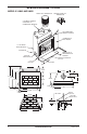
SPECIFICATIONS Continued MODELS VJM36 AND JM36 ROUND TOP TERMINATION SQUARE CHASE-TOP TERMINATION 1" CHIMNEY AIRSPACE CLEARANCE TO COMBUSTIBLE MATERIAL NO COMBUSTIBLE MATERIAL ON FACE COMBUSTIBLE WALL BOARD 11/2" AIR SPACE BACK AND SIDES OUTSIDE AIR MINIMUM 12" TO PERPENDICULAR SIDEWALL GAS LINE KNOCKOUTS HEARTH EXTENSION 60" X 20" 12" EACH SIDE 0" TO BOTTOM 29.00 12.000 7.500 67.000 22.000 58.000 26.625 49.000 30.000 0.625 45.000 36.000 8.000 1.000 45.
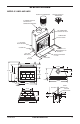
SPECIFICATIONS Continued MODELS VJM42 AND JM42 ROUND TOP TERMINATION SQUARE CHASE-TOP TERMINATION 2" CHIMNEY AIRSPACE CLEARANCE TO COMBUSTIBLE MATERIAL NO COMBUSTIBLE MATERIAL ON FACE COMBUSTIBLE WALL BOARD 11/2" AIR SPACE BACK AND SIDES OUTSIDE AIR MINIMUM 18" TO PERPENDICULAR SIDEWALL GAS LINE KNOCKOUTS HEARTH EXTENSION 66" X 20" 0" TO BOTTOM 12" EACH SIDE 12.000 30.500 11.000 67.000 58.000 49.000 21.250 30.000 28.500 0.625 51.000 42.000 8.000 1.000 51.
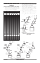
SPECIFICATIONS MODELS VJM50 AND JM50 ROUND TOP TERMINATION SQUARE CHASE-TOP TERMINATION 2" CHIMNEY AIRSPACE CLEARANCE TO COMBUSTIBLE MATERIAL NO COMBUSTIBLE MATERIAL ON FACE COMBUSTIBLE WALL BOARD 11/2" AIR SPACE BACK AND SIDES OUTSIDE AIR MINIMUM 18" TO PERPENDICULAR SIDEWALL GAS LINE KNOCKOUTS 0" TO BOTTOM 12" EACH SIDE HEARTH EXTENSION 74" X 20" 12.000 38.500 11.000 67.000 21.250 58.000 49.000 30.000 28.500 0.625 59.000 50.000 8.000 1.000 59.000 LEFT SIDE 32.
FIREPLACE INSTALLATION FRAMING SELECTING LOCATION To determine the safest and most efficient location for the fireplace, you must take into consideration the following guidelines: 1. The location must allow for proper clearances (see Figures 1 and 2). 2. Consider a location where the fireplace will not be affected by drafts, air conditioning ducts, windows or doors. 3. A location that avoids the cutting of joists or roof rafters will make installation easier. 4.
FIREPLACE INSTALLATION MANTELS Continued Note: For outdoor installations, the fireplace enclosure must allow for adequate drainage and fresh air ventilation. It is recommended that a sealed, corrosion resistant catch pan with provision for drainage be installed under the fireplace within the fireplace enclosure. HEARTH EXTENSION A mantel may be installed if desired (see Figure 4).
VENTING INSTALLATION PART NO. OPTIONAL OUTSIDE AIR KIT (MODEL AK4/AK4F) The installation of an outside air kit should be performed during the rough framing of the fireplace due to the nature of it's location. Outside combustion air is accessed through a vented crawl space (AK4F) or through a sidewall (AK4). CAUTION: Combustion air inlet ducts shall not terminate in attic space. Secure to Collars with Metal Tape, Screws or Straps (Min.
VENTING INSTALLATION Continued USING ELBOW OFFSETS (30E-12DM) 1. To achieve desired offset, you may install combinations of 12, 18, 24, 36 and 48" length of double wall pipe (see offset chart and Figure 7).
VENTING INSTALLATION Continued Screws B A Figure 9 - Elbow Offset PENETRATING THE ROOF To maintain a 1" (JM36) or 2" (JM42/JM50) clearance to the pipe on a roof with a pitch, a rectangular opening must be cut. 1. Determine the center point through which the pipe will penetrate the roof. 2. Determine the center point of the roof. Pitch is the distance the roof drops over a given span, usually 12". A 6/12 pitch means that the roof drops 6" for each 12" one measure horizontally down from the roof rafters.
VENTING INSTALLATION Continued 4. Remove the shingles around the opening measured. Cut out this section. 5. Add the next sections of the pipe until the end penetrates the roof line. Check to see that the proper clearances are maintained. Extend chimney by adding sections of double wall pipe until pipe is minimum of 30" above the highest point of the roof cutout. Termination and chimney must extend a minimum of 36" above the highest point where it passes through the roof.
VENTING INSTALLATION Continued CHASE INSTALLATIONS Instructions for chase installations are included with the chase style termination chosen. In a multiple chase installation, be sure to provide adequate distance between terminations to prevent smoke spillage from one termination to another. We suggest that terminations be separated at least 24", center to center and stacked at a vertical height difference of 18" (see Figure 16).
OPTIONAL GAS LINE INSTALLATION Continued CAUTION: All gas piping and connections must be tested for leaks after the installation is completed. After ensuring that the gas valve is on, apply soap and water solution to all connections and joints. Bubbles forming show a leak. Correct all leaks at once. DO NOT USE AN OPEN FLAME FOR LEAK TESTING AND DO NOT OPERATE ANY APPLIANCE IF A LEAK IS DETECTED. LEAK TESTING SHOULD BE DONE BY A QUALIFIED SERVICE PERSON.
BRICK INSTALLATION Continued Install the bricks one at a time starting with the hearth panel followed by the rear panel and then the left or right panel. It is important to install the bricks in sequence. Note: The left and right panels have identical bricks. Please note, full size bricks are NOT stamped. Use brick “AO” (JM42 and JM50 only) or “AR” (JM36 only) if an optional gas line is installed. Mount brick “AO” or “AR” as shown in Figure 20.
BRICK INSTALLATION Continued BRICK INSTALLATION FOR MODEL (V)JM42 LEFT PANEL Q O D D FULL D FULL FULL C FULL FULL E B F FULL A FULL F A F FULL B O C D FULL C FULL FULL D FULL AT AM D FULL FULL FULL B E AL AM Q R E FULL FULL F B AN FULL FULL F B Z Q E A FULL FULL F B A FULL C Z R FULL FULL C RIGHT PANEL REAR PANEL C AP AP **AO **AO OR OR V FULL FULL W X AA FULL K L FULL Y V FULL FULL K L **See instruction on page 14 before installi
BRICK INSTALLATION Continued BRICK MATRIX - (V)JM36 BRICK MATRIX FOR MODEL (V)JM36 BRICK MATRIX Full A B Box #1 Hearth-36 8 - - Box #2 Rear-36 7 - - Box #3 Left or Right-36 5 - - Box #3 Left or Right-36 5 - TOTAL 25 0 C D E F G H I J K L M N O P - - - - 2 2 2 - - 3 2 - - - 6 4 - - - - - - - - - - - - - - - - - - - - - - - - - 1 - - - - - - - - - - - - - - 1 0 6 4 0 0 2 2 2 0 0 3 2 0 0 2 BRICK MATRIX F
BRICK INSTALLATION Continued BRICK MATRIX - (V)JM42 BRICK MATRIX FOR MODEL (V)JM42 BRICK MATRIX Full A B C D Box #1 Hearth-42 10 - - - - Box #2 Rear-42 8 - - - - Box #3 Left or Right-42 8 2 3 3 3 Box #3 Left or Right-42 8 2 3 3 TOTAL 34 4 6 6 E F G H I J K L M N O P - - - - - - 4 4 - - - - 4 6 - - - - - - - - - - - - - - - - - - - - 1 - 3 - - - - - - - - - - 1 - 6 4 6 0 0 0 0 4 4 0 0 2 0 BRICK MATRIX
BRICK INSTALLATION Continued BRICK MATRIX - (V)JM50 BRICK MATRIX FOR MODEL (V)JM50 BRICK MATRIX Full A B C D Box #1 Hearth-50 12 - - - - Box #2 Rear-50 12 - - - - Box #3 Left or Right-50 8 2 3 3 3 Box #3 Left or Right-50 8 2 3 3 3 TOTAL 40 4 6 6 6 E F G H I J K L M N O P - - 2 2 2 2 4 4 2 2 - - 6 4 - - - - - - - - - 2 - - - - - - - - - - 1 - - - - - - - - - - - 1 - 6 4 2 2 2 2 4 4 2 2 2 2 BRICK MATRIX
BRICK INSTALLATION Continued INSTALLING Z-SHAPED GRATE RETAINER BRACKET Before grouting the bricks, locate the z-shaped grate retainer brackets on top of the hearth bricks as shown in Figure. Position the retainer brackets at 8 3/4" apart from center to center of notch. Model JM50 JM42 JM36 Distance Apart 8 3/4" Centers 4 1/4" Centers 3 1/4" Centers See Chart for Grate Retainer Brackets Location Figure 22 - Installing Grate Retainer Bracket GROUTING INSTRUCTIONS Material provided: 2 - 9 lb.
GLASS DOOR INSTALLATION INSTALLING GLASS DOORS IMPORTANT: Install glass door frame first before installing glass door. DOOR FRAME ASSEMBLY Inset L-shaped gussets starting at the left top portion of door frame. Gusset holes should align with screw holes on the frame. Secure using flat head screws. Flat Head Screw Top Spring clips have been installed but some adjustments may be needed. Install the doors using the following steps: 1.
OPERATION AND MAINTENANCE GUIDELINES GLASS DOORS Glass doors are optional with the fireplace. When the fireplace is in operation, doors must be fully opened or fully closed position only or a fire hazard may be created (see Figure 28). A fireplace equipped with glass doors operates mush differently than a fireplace with an open front. A fireplace with glass doors has a limited amount of air for combustion.
OPERATION AND MAINTENANCE GUIDELINES Continued WARNING: Risk of fire! Replace grate with DESA model 111754-02 JM50, 117544-01 JM42, 117544-03 JM36 grate only. This grate has been designed to keep the operation of your fireplace safe and efficient. TECHNICAL SERVICE You may have further questions about installation, operation, or troubleshooting. If so, contact DESAʼs Technical Service Department at 1-866-672-6040. When calling please have your model and serial numbers of your heater ready.
REPLACEMENT AND ACCESSORY PARTS DOUBLE WALL PIPE 12-12DM 18-12DM 24-12DM 12-12HT 18-12HT 24-12HT BDM36E 36" BI-FOLD MASONRY DOOR-EBONY BI-FOLD GLASS DOOR BDM36G 36" BI-FOLD MASONRY DOOR-PEWTER BDM36C 36" BI-FOLD MASONRY DOOR-OILED BRONZE BDM42E 42" BI-FOLD MASONRY DOOR-EBONY BDM42G 42" BI-FOLD MASONRY DOOR-PEWTER BDM42C 42" BI-FOLD MASONRY DOOR-OILED BRONZE BDM50E 50" BI-FOLD MASONRY DOOR-EBONY 36-12DM 48-12DM BDM50G 50" BI-FOLD MASONRY DOOR-PEWTER 36-12HT 48-12HT 30° OFFSET AND RETURN BDM50C 50" B
2701 Industrial Drive P.O. Box 90004 Bowling Green, KY 42102-9004 www.desatech.com 117541 01 NOT A UPC 117541-01 Rev.