UNVENTED (VENT-FREE) GAS LOG HEATER OWNER’S OPERATION AND INSTALLATION MANUAL VF-30N-PJD, VF-30P-PJD VF-24N-PJD, VF-24P-PJD VF-18N-PJD, VF-18P-PJD WARNING: If the information in this manual is not followed exactly, a fire or explosion may result causing property damage, personal injury or loss of life. — Do not store or use gasoline or other flammable vapors and liquids in the vicinity of this or any other appliance. — WHAT TO DO IF YOU SMELL GAS • Do not try to light any appliance.
TABLE OF CONTENTS Safety Information................................................ 2 Product Identification............................................ 4 Local Codes......................................................... 5 Unpacking............................................................ 5 Product Features.................................................. 5 Air For Combustion and Ventilation...................... 5 Installation............................................................
safety information Continued WARNING: This product contains and/or generates chemicals known to the State of California to cause cancer or birth defects or other reproductive harm. IMPORTANT: Read this owner’s manual carefully and completely before trying to assemble, operate or service this heater. Improper use of this heater can cause serious injury or death from burns, fire, explosion, electrical shock and carbon monoxide poisoning.
safety information Continued 1. This appliance is only for use with the type of gas indicated on the rating plate. This appliance is not convertible for use with other gases. 2. Do not place propane/LP supply tank(s) inside any structure. Locate propane/LP supply tank(s) outdoors (propane/LP units only). 3.
Local Codes Install and use heater with care. Follow all local codes. In the absence of local codes, use the latest edition of The National Fuel Gas Code ANSI Z223.1/NFPA 54*. *Available from: American National Standards Institute, Inc. 1430 Broadway New York, NY 10018 National Fire Protection Association, Inc. Batterymarch Park Quincy, MA 02269 Unpacking CAUTION: Do not remove the data plates from the grate assembly. The data plates contain important warranty and safety information. 1.
air for combustion and ventilation Continued Unusually tight construction is defined as construction where: a. walls and ceilings exposed to the outside atmosphere have a continuous water vapor retarder with a rating of one perm (6 x 10-11 kg per pa-sec-m2) or less with openings gasketed or sealed and b. weather stripping has been added on openable windows and doors and c.
air for combustion and ventilation Continued If the actual Btu/Hr used is less than the maximum Btu/Hr the space can support, the space is an unconfined space. You will need no additional fresh air ventilation. WARNING: If the area in which the heater may be operated is smaller than that defined as an unconfined space or if the building is of unusually tight construction, provide adequate combustion and ventilation air by one of the methods described in the National Fuel Gas Code, ANSI Z223.
Installation NOTICE: This heater is intended for use as supplemental heat. Use this heater along with your primary heating system. Do not install this heater as your primary heat source. If you have a central heating system, you may run system’s circulating blower while using heater. This will help circulate the heat throughout the house. In the event of a power outage, you can use this heater as your primary heat source. WARNING: A qualified service person must install heater. Follow all local codes.
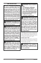
Installation Continued Example installation and clearances for vent-free operation WARNING: Maintain the minimum clearances. If you can, provide greater clearances from floor, ceiling and adjoining wall.
INSTALLATION Continued Noncombustible Material Distance (A) 12" or more Between 8" and 12" Less than 8" Requirements for Safe Installation Noncombustible material OK. 24" Model:Install fire place hood accessory (GA6060, see Accessories, page 25). 18" Model: Noncombustible material OK Noncombustible material must be extended to at least 8". See Between 8" and 12", above. If you cannot extend material, you must operate heater with flue damper open.
INSTALLATION Continued Mantel Clearances In addition to meeting noncombustible material clearances, you must also meet required clearances between fireplace openings and mantel shelf on each side of the fireplace. If you do not meet the clearances listed below, you will need a hood. Determining Minimum Mantel Clearance If you meet minimum clearance between mantel shelf and top of fireplace opening, a hood is not required (see Figure 6, page 10).
INSTALLATION Continued Installation Items Needed • control cover kit (provided with heater) • approved flexible gas hose (not provided) (if allowed by local codes) • sealant (resistant to propane/LP gas, not provided) 1. Apply pipe joint sealant lightly to male threads of gas fitting (not provided). Connect approved flexible gas hose to inlet side of gas control (see Figure 10). IMPORTANT: Hold gas fitting with wrench when connecting flexible gas hose. 2. Position heater assembly in fireplace. 3.
INSTALLATION Continued Installation must include an equipment shutoff valve, union and plugged 1/8" NPT tap. Locate NPT tap within reach for test gauge hook up. NPT tap must be upstream from heater (see Figure 12). IMPORTANT: Install equipment shutoff valve in an accessible location. The equipment shutoff valve is for turning on or shutting off the gas to the appliance. Check your building codes for any special requirements for locating equipment shutoff valve to fireplaces.
Installation Propane/LP Supply Tank Continued 3. Pressurize supply piping system by either opening propane/LP supply tank valve for propane/LP gas or opening main gas valve located on or near gas meter for natural gas or using compressed air. 4. Check all joints of gas supply piping system. Apply noncorrosive leak detection fluid to all joints. Bubbles forming show a leak. 5. Correct all leaks at once. 6. Reconnect heater and equipment shutoff valve to gas supply. Check reconnected fittings for leaks.
Operating Heater Continued WHAT TO DO IF YOU SMELL GAS • Do not try to light any appliance. • Do not touch any electric switch; do not use any phone in your building. • Immediately call your gas supplier from a neighbor’s phone. Follow the gas supplier’s instructions. • If you cannot reach your gas supplier, call the fire department. C. Use only your hand to push in or turn the gas control knob. Never use tools.
Operating Heater Continued Changing The Code The control is radio frequency operated. A code (chosen from among 4,000 available codes) is preset for all valves, but can be changed if required (15 additional codes available). Change DIP switch position. (The DIP switch is located inside the hand held control at the top of the battery compartment.) Then press the receiver's reset button until you hear a second (longer) signal. When pressing the button on the remote handset in the following 20 sec.
Operating Heater Continued Set Timer • Switch to timer mode by pressing the SET button briefly. • Press the SET button until P1 flashes. • Set the hours with and minutes with . • Press SET briefly for the next burner cycle time. • If all 4 times are set, pressing the OFF button or waiting will complete the programming. to turn gas off to appliance Shutting Off Heater Press OFF button on remote control to switch off main gas and pilot gas.
Operating Heater Continued 10. Continue holding down metal core for about 10 seconds and then release the metal core. Pilot should stay lit. If not, repeat steps one through 4, page 17. 11. Turn MAN knob to ON position - main gas flows. 12. Turn Motor-knob to adjust flame. Knob has a slipping clutch that allows manual flame height adjustment.
Cleaning and Maintenance WARNING: Turn off heater and let cool before cleaning. CAUTION: You must keep control areas, burner and circulating air passageways of heater clean. Inspect these areas of heater before each use. Have heater inspected yearly by a qualified service person. Heater may need more frequent cleaning due to excessive lint from carpeting, bedding material, pet hair, etc. 1. Remove the two screws that hold the front log bracket onto the assembly (see Figure 23).
Troubleshooting WARNING: Turn off heater and let cool before servicing. Only a qualified service person should service and repair heater. CAUTION: Never use a wire, needle or similar object to clean ODS/pilot. This can damage ODS/pilot unit. Note: All troubleshooting items are listed in order of operation. OBSERVED PROBLEM POSSIBLE CAUSE REMEDY When and are pressed at the same time, there is no spark at ODS/pilot 1. Ignitor electrode not connected to ignitor cable 2. Ignitor cable pinched or wet 1.
troubleshooting OBSERVED PROBLEM Continued POSSIBLE CAUSE Burner backfiring during combustion 1. Burner orifice is clogged or damaged 2. Damaged burner 3. Gas regulator defective Orange flame in burner during burner combustion 1. Not enough air REMEDY 1. Clean burner (see Cleaning and Maintenance, page 19) or replace burner orifice 2. Replace damaged burner 3. Replace gas regulator 2. Gas regulator defective 1. Check burner for dirt and debris.
troubleshooting Continued WARNING: If you smell gas • Shut off gas supply. • Do not try to light any appliance. • Do not touch any electrical switch; do not use any phone in your building. • Immediately call your gas supplier from a neighbor’s phone. Follow the gas supplier’s instructions. • If you cannot reach your gas supplier, call the fire department. IMPORTANT: Operating heater where impurities in air exist may create odors.
troubleshooting Continued Identifying error signals from reciever OBSERVED PROBLEM POSSIBLE CAUSE REMEDY Long signals (0.8 second tone, 0.2 second break) during ignition Battery nearly down. (When signal appears the first time approximately 10 ignitions left) Replace battery 5 second continuous tone Cable is not connected, ON/OFF switch is in OFF position Connect cables 5 short signals (8.2 second tone, 0.2 second break) Ignition not successful, possible air in supplyline Swit to ON.
Service Hints When Gas Pressure Is Too Low • pilot will not stay lit • burners will have delayed ignition • heater will not produce specified heat • propane/LP gas supply may be low You may feel your gas pressure is too low. If so, contact your local propane/LP or natural gas supplier. Technical Service You may have further questions about installation, operation, or troubleshooting. If so, contact DESA’s Technical Service Department at 1-866-672-6040.
Specifications VF-18N-PJD Btu (Variable) 21,000/30,000 Type Gas Natural Gas Only Ignition Piezo Manifold Pressure 3.5" W.C. Inlet Gas Pressure (in. of water) Maximum 10.5" W.C. Minimum* 5.0" W.C. Shipping Weight 32 lbs. * For purpose of input adjustment VF-24N-PJD/VF-30N-PJD 21,000/39,000 Natural Gas Only Piezo 3.5" W.C. VF-18P-PJD Btu (Variable) 21,000/30,000 Type Gas Propane/LP Only Ignition Piezo Manifold Pressure 10" W.C. Inlet Gas Pressure (in. of water) Maximum 14" W.C. Minimum* 11" W.C.
Illustrated Parts Breakdown Models VF-18N-PJD and vf-18p-pjd 6 3 4 18 24 5 24 11 9 13 17 19 22 23 24 14 24 1 15 12 11 24 10 7 8 20 16 24 2 24 21 24 26 www.desatech.
Parts List This list contains replaceable parts used in your heater. When ordering parts, follow the instructions listed under Replacement Parts on page 24 of this manual. KEY NO.
Illustrated Parts Breakdown Models VF-24N-PJD and vf-24p-pjd 25 7 23 24 20 19 3 6 13 8 12 11 10 25 17 21 4 18 25 11 9 14 15 25 5 25 16 1 2 25 22 28 www.desatech.
Parts List This list contains replaceable parts used in your heater. When ordering parts, follow the instructions listed under Replacement Parts on page 24 of this manual. KEY NO.
Illustrated Parts Breakdown Models VF-30N-PJD and vf-30p-pjd 22 23 20 25 7 24 12 11 10 24 8 19 17 3 6 13 4 18 24 11 9 14 1 5 15 16 24 24 2 24 21 30 www.desatech.
Parts List This list contains replaceable parts used in your heater. When ordering parts, follow the instructions listed under Replacement Parts on page 24 of this manual. KEY NO.
Warranty Information KEEP THIS WARRANTY Model Serial No. Date Purchased Always specify model and serial numbers when communicating with the factory. We reserve the right to amend these specifications at any time without notice. The only warranty applicable is our standard written warranty. We make no other warranty, expressed or implied.