UNVENTED (VENT FREE) GAS LOG HEATER OWNER’S OPERATION AND INSTALLATION MANUAL ANSI Z21.11.2b-2004 ANSI Z21.60-2003 APPROVED Models VFRMV18NB, VFRMV18PB, VFRMV24NB and VFRMV24PB Vent-free Models Also Design-Certified As Vented Decorative Appliances WARNING: If the information in this manual is not followed exactly, a fire or explosion may result causing property damage, personal injury or loss of life.
WARNING: Improper installation, adjustment, alteration, service or maintenance can cause injury or property damage. Refer to this manual for correct installation and operational procedures. For assistance or additional information consult a qualified installer, service agency or the gas supplier. WARNING: This appliance is for installation only in a solid-fuel burning masonry or UL127 factory-built fireplace or in a listed ventless firebox enclosure.
Safety Information WARNING: This product contains and/or generates chemicals known to the State of California to cause cancer or birth defects, or other reproductive harm. IMPORTANT: Read this owner’s manual carefully and completely before trying to assemble, operate or service this log set. Improper use of this log set can cause serious injury or death from burns, fire, explosion, electrical shock and carbon monoxide poisoning.
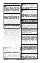
SAFETY INFORMATION Continued Keep the appliance area clear and free from combustible materials, gasoline and other flammable vapors and liquids. Solid fuels shall not be burned in a fireplace in which an unvented room heater installed. Children and adults should be alerted to the hazard of high temperature and should stay away to avoid burns or clothing ignition. 1. This appliance, as supplied, is only for use with the type of gas indicated on the rating plate.
Product Identification Log Set Chassis Assembly Figure 1 - Product Identification Local Codes Install and use the heater with care. Follow all local codes. In the absence of local codes, use the latest edition of the National Fuel Gas Code ANSI Z223.1/NFPA 54* *Available from: American National Standards Institute, Inc. 1430 Broadway New York, NY 10018 National Fire Protection Association, Inc.
Air For Combustion and Ventilation WARNING: This heater shall not be installed in confined space or unusually tight construction unless provisions are provided for adequate combustion and ventilation air. Read the following instructions to insure proper fresh air for this and other fuel-burning appliances in your home. Today’s homes are built more energy efficient than ever. New materials, increased insulation and new construction methods help reduce heat loss in homes.
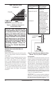
AIR FOR COMBUSTION AND VENTILATION Continued 1. Determine the volume of the space (length x width x height). Length x Width x Height =__________cu. ft. (volume of space) Example: Space size 20 ft. (length) x 16 ft. (width) x 8 ft. (ceiling height) = 2560 cu. ft. (volume of space) If additional ventilation to adjoining room is supplied with grills or openings, add the volume of these rooms to the total volume of the space. 2.
AIR FOR COMBUSTION AND VENTILATION Continued 12" Ventilation Grills Into Adjoining Room, Option 1 Ventilation Grills Into Adjoining Room, Option 2 Or Remove Door into Adjoining Room, Option 3 12" Figure 2 - Ventilation Air from Inside Building Ventilation Air From Outdoors Provide extra fresh air by using ventilation grills or ducts. You must provide two permanent openings: one within 12" of the ceiling and one within 12" of the floor.
Installation Continued WARNING: Seal any fresh air vents or ash clean-out doors located on floor or wall of fireplace. If not, drafting may cause pilot outage or sooting. Use a heat-resistant sealant. Do not seal chimney flue damper.
Installation Noncombustible Requirements for Material Distance (A) Safe Installation 12" or more Noncombustible material OK. Continued Example * Between 8" and 12" 24" Models: Install fireplace hood accessory (GA6050, GA6052, GA6053, see Accessories, page 26). 18" Model: Noncombustible material OK. Less than 8" Noncombustible material must be extended to at least 8". See Between 8" and 12", above.
Installation Continued Mantel Clearances In addition to meeting noncombustible material clearances, you must also meet required clearances between fireplace opening and mantel shelf. If you do not meet the clearances listed below, you will need a hood. Determining Minimum Mantel Clearance If you meet minimum clearance between mantel shelf and top of fireplace opening, a hood is not required (see Figure 6).
Installation Continued INSTALLING DAMPER CLAMP ACCESSORY FOR VENTED OPERATION Note: When used as a vented decorative, appliance must be installed only in a solid-fuel burning fireplace with a working flue and constructed of noncombustible material. If your heater is a non-thermostatically-controlled model, you may use this heater as a vented product. There are three reasons for operating your heater in the vented mode. 1.
Installation Continued CAUTION: Do not pick up heater assembly by logs. This could damage unit. Only handle assembly by grates. IMPORTANT: Make sure the heater burners are level. If heater is not level, heater will not work properly.
Installation Continued CAUTION: Use only new, black iron or steel pipe. Internally-tinned copper tubing may be used in certain areas. Check your local codes. Use pipe of 1/2" diameter or greater to allow proper gas volume to heater. If pipe is too small, undue loss of volume will occur. Installation must include an equipment shutoff valve, union and plugged 1/8" NPT tap. Locate NPT tap within reach for test gauge hook up. NPT tap must be upstream from heater (see Figure 14).
Installation Propane/LP Supply Tank Continued Equipment Shutoff Valve Piping System Test Pressures In Excess Of 1/2 PSIG (3.5 kPa) 1. Disconnect appliance with its appliance main gas valve (control valve) and equipment shutoff valve from gas supply piping system. Pressures in excess of 1/2 psig will damage heater regulator. 2. Cap off open end of gas pipe where equipment shutoff valve was connected. 3.
Operating Heater FOR YOUR SAFETY READ BEFORE LIGHTING WARNING: If you do not follow these instructions exactly, a fire or explosion may result causing property damage, personal injury or loss of life. A. This appliance has a pilot which must be lighted by hand. When lighting the pilot, follow these instructions exactly. B. BEFORE LIGHTING smell all around the appliance area for gas. Be sure to smell next to the floor because some gas is heavier than air and will settle on the floor.
OPERATING HEATER Continued 4. Press in and turn control knob clockwise to the OFF position (see Figure 18). WARNING: Burners will come on automatically within one minute when the switch is in the ON position after the pilot is lit. 5. Wait five (5) minutes to clear out any gas. Then smell for gas, including near the floor. If you smell gas, STOP! Follow “B” in the safety information in column 1, page 16. If you don’t smell gas, go to the next step. 6.
OPERATING HEATER Continued MANUAL LIGHTING PROCEDURE 1. Follow steps 1 through 6 under Lighting Instructions, page 16. 2. Depress control knob and light pilot with match. 3. Keep control knob pressed in for 30 seconds after lighting pilot. After 30 seconds, release control knob. Now follow steps 9 through 11, Lighting Instructions, page 17. Optional Hand-Held REMOTE OPERATION Note: All remote control accessories must be purchased separately (see Accessories, page 26).
OPERATING HEATER Continued 4. Press the POWER and LOCK buttons together to turn off the fireplace. Note: Do not leave the hand-held remote in the AUTO mode close to the fireplace. The radiant heat from the fireplace will turn off the fireplace. Ideally, place the hand-held remote in the center of the room facing towards the fireplace. Note: Do not hold the hand-held remote for a long time. Body temperature will affect its operation in the AUTO mode.
Inspecting Burners Continued BURNER FLAME PATTERN Figure 25 shows correct burner flame pattern. NOTICE: Do not mistake orange flames with yellow tipping. Dirt or other fine particles are burned by heater, causing brief patches of orange flame.
CLEANING AND MAINTENANCE Pilot Air Inlet Hole Continued 1. Shut off the unit, including the pilot. Allow the unit to cool for at least thirty minutes. 2. Inspect burner, pilot and primary air inlet opening on injector holder for dust and dirt (see Figure 27). 3. Blow air through the ports/slots and holes in the burner. 4. Check the injector holder located at the end of the burner tube again. Remove any large particles of dust, dirt, lint or pet hair with a soft cloth or vacuum cleaner nozzle. 5.
Troubleshooting WARNING: Turn off and unplug heater and let cool before servicing. Only a qualified service person should service and repair heater. CAUTION: Never use a wire, needle or similar object to clean ODS/pilot. This can damage ODS/pilot unit. Note: All troubleshooting items are listed in order of operation. OBSERVED PROBLEM POSSIBLE CAUSE REMEDY When ignitor button is pressed, 1. Ignitor electrode not con- 1. Reconnect ignitor cable there is no spark at ODS/pilot nected to ignitor cable 2.
TROUBLESHOOTING OBSERVED PROBLEM Continued POSSIBLE CAUSE REMEDY ODS/pilot lights but flame goes 1. Control knob not fully pressed in 1. Press in control knob fully out when control knob is re- 2. Control knob not pressed in 2. After ODS/pilot lights, keep leased long enough control knob pressed in 30 seconds 3. Safety interlock system has 3. Wait one minute for safety inbeen triggered terlock system to reset. Repeat ignition operation 4. Equipment shutoff valve not 4.
TROUBLESHOOTING Continued OBSERVED PROBLEM POSSIBLE CAUSE Orange flame in burner during 1. Not enough air burner combustion 2. Gas regulator defective REMEDY 1. Check burner(s) for dirt and debris. If found, clean burner(s) (see Cleaning and Maintenance, page 20) 2. Replace gas regulator Slight smoke or odor during initial 1. Residues from manufacturing 1. Problem will stop after a few operation processes and logs curing hours of operation Heater produces a whistling noise 1.
TROUBLESHOOTING Continued WARNING: If you smell gas • Shut off gas supply. • Do not try to light any appliance. • Do not touch any electrical switch; do not use any phone in your building. • Immediately call your gas supplier from a neighbor’s phone. Follow the gas supplier’s instructions. • If you cannot reach your gas supplier, call the fire department. IMPORTANT: Operating heater where impurities in air exist may create odors.
Specifications VFRMV18NB VFRMV24NB VFRMV18PB VFRMV24PB • • • • • • • • • • Rating (Variable): 20,000/30,000 Btu/Hr Gas Type: Natural Gas Only Ignition: Piezo Manifold Pressure: 3.5" - 1.6" W.C. Inlet Gas Pressure (in. of water): Maximum 10.5" W.C., Minimum* 5.0" W.C. Rating (Variable): 23,000/30,000 Btu/Hr Gas Type: Propane/LP Only Ignition: Piezo Manifold Pressure: 10" - 6.3" W.C. Inlet Gas Pressure (in. of water): Maximum 14" W.C., Minimum* 11" W.C.
ACCESSORIES VENT-FREE LOGMATE® FIREBOXES (Not Shown) Continued Available in 32", 36" and 42" models. Circulating fireboxes feature louvers and an optional blower. Non-circulating, smooth face models are ideal for custom trim applications such as stone or marble. FIREPLACE HOOD Black - GA6050 Brass - GA6052 Antique Brass - GA6053 For all models. Helps deflect heat away from mantel or wall above fireplace. Fits openings 28" to 48" wide.
Illustrated Parts Breakdown Models VFRMV18NB, VFRMV18PB, VFRMV24NB (Shown) and VFRMV24PB 3a 2 3b 5 9 4 6 11 12 13 1 19 22 10 14 8 16 7 18 17 15 20 28 www.desatech.
PARTS LIST 3b 4 5 6 7 8 9 10 11 12 13 14 15 16 17 18 19 20 21 ** 111800-01 116515-01 116516-01 116515-02 116516-02 111803-05 111803-06 111803-07 111803-02 111803-04 111816-01 111817-01 14396 111804-01 111804-03 111819-04 111819-05 111819-14 111819-15 111807-01 111807-02 111796-01 097159-04 103784-01 103784-02 14579 111817-02 111796-02 112376-01 103778-01 111828-01 111824-01 Description Grate Assembly Screw Front Log Assembly Front Log Assembly Rear Log Assembly Rear Log Assembly Right Burner Bracket R
NOTES _____________________________________________________ ______________________________________________________ ______________________________________________________ ______________________________________________________ ______________________________________________________ ______________________________________________________ ______________________________________________________ ______________________________________________________ ______________________________________________________ ___________
NOTES _____________________________________________________ ______________________________________________________ ______________________________________________________ ______________________________________________________ ______________________________________________________ ______________________________________________________ ______________________________________________________ ______________________________________________________ ______________________________________________________ ___________
Warranty Information KEEP THIS WARRANTY Model Serial No. Date Purchased Always specify model and serial numbers when communicating with the factory. We reserve the right to amend these specifications at any time without notice. The only warranty applicable is our standard written warranty. We make no other warranty, expressed or implied.