
OWNER'S OPERATION AND INSTALLATION MANUAL UNVENTED (VENT-FREE) GAS LOG HEATER VRL24NR, VRL24PR, VRL30NR, VRL30PR, CSG3924NR, CSG3924PR CTB3924NR, CTB3924PR 24" and 30" Thermostat Models: VRL24NT, VRL24PT, VRL30NT, VRL30PT, CSG3924NT, CSG3924PT CTB3924NT, CTB3924PT


110021-01A
For more information, visit www.desatech.com
For more information, visit www.desatech.com
14
ON
POSITION
OFF
POSITION
INSTALLATION
Continued
WARNING: Test all gas piping and connections
for leaks after installing or servicing. Correct all
leaks at once.
WARNING: Never use an open flame to check for
a leak. Apply a noncorrosive leak detection fluid to all
joints. Bubbles forming show a leak. Correct all leaks
at once.
CAUTION: Make sure external regulator has been
installed between propane/LP supply and heater. See
guidelines under
Connecting to Gas Supply
, page 12.
Pressure Testing gas Supply Piping system
Test Pressures In Excess Of 1/2 PSIG (3.5 kPa)
1. Disconnect appliance with its appliance main gas valve (control
valve) and equipment shutoff valve from gas supply piping sys-
tem. Pressures in excess of 1/2 psig will damage heater regulator.
2. Cap off open end of gas pipe where equipment shutoff valve
was connected.
3. Pressurize supply piping system by either opening propane/LP
supply tank valve for propane/LP gas or opening main gas valve
located on or near gas meter for natural gas, or using com-
pressed air.
4. Check all joints of gas supply piping system. Apply a noncorrosive
leak detection fluid to all joints. Bubbles forming show a leak.
5. Correct all leaks at once.
6. Reconnect heater and equipment shutoff valve to gas supply.
Check reconnected fittings for leaks.
Test Pressures Equal To or Less Than 1/2 PSIG (3.5 kPa)
1. Close equipment shutoff valve (see Figure 17).
2. Pressurize supply piping system by either opening propane/LP sup-
ply tank valve for propane/LP gas or opening main gas valve lo-
cated on or near gas meter for natural gas, or using compressed air.
3. Check all joints from gas meter for natural or propane/LP sup-
ply to equipment shutoff valve (see Figure 18 or 19). Apply a
noncorrosive leak detection fluid to all joints. Bubbles form-
ing show a leak.
4. Correct all leaks at once.
CHECKING GAS CONNECTIONS
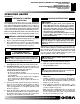
Figure 17 - Equipment Shutoff Valve
Figure 18 - Checking Gas Joints (Propane/LP Gas Only)
Thermostat Gas Valve or
Control Valve Location
Propane/LP
Supply Tank
Equipment Shutoff Valve
Open
Closed
Equipment
Shutoff
Valve
Pressure Testing Heater Gas Connections
1. Open equipment shutoff valve (see Figure 17).
2. Open main gas valve located on or near gas meter for natural
gas or open propane/LP supply tank valve.
3. Make sure control knobs of heater are in the OFF position.
4. Check all joints from equipment shutoff valve to thermostat gas
valve (Thermostat-Controlled Models) or control valve (Remote-
Ready Models) (see Figure 18 or 19). Apply a noncorrosive
leak detection fluid to all joints. Bubbles forming show a leak.
5. Correct all leaks at once.
6. Light heater (see Operating Heater, pages 17 through 21).
Check all other internal joints for leaks.
7. Turn off heater (see To Turn Off Gas to Appliance, page 18 [Ther-
mostat-Controlled Models] or page 20 [Remote-Ready Models]).
INSTALLATION
Checking Gas Connections
Figure 19 - Checking Gas Joints (Natural Gas Only)
Thermostat Gas Valve or
Control Valve Location
Gas Meter
Equipment Shutoff Valve