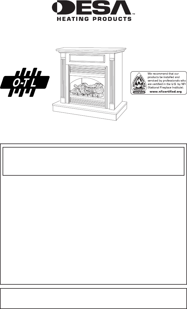
UNVENTED (VENT-FREE) GAS FIREPLACE SYSTEM OWNER’S OPERATION AND INSTALLATION MANUAL Thermostatically-controlled MODELS VSGF28NTF and VSGF28PTF WARNING: If the information in this manual is not followed exactly, a fire or explosion may result causing property damage, personal injury or loss of life. — Do not store or use gasoline or other flammable vapors and liquids in the vicinity of this or any other appliance. — WHAT TO DO IF YOU SMELL GAS • Do not try to light any appliance.
Table of Contents Safety Information................................................ 2 Local Codes......................................................... 4 Product Identification............................................ 5 Unpacking............................................................ 5 Product Features.................................................. 5 Air For Combustion and Ventilation...................... 6 Installation............................................................
SAFETY INFORMATION Continued WARNING: This product contains and/or generates chemicals known to the state of California to cause cancer or birth defects or other reproductive harm. IMPORTANT: Read this owner’s manual carefully and completely before trying to assemble, operate or service this heater. Improper use of this heater can cause serious injury or death from burns, fire, explosion, electrical shock and carbon monoxide poisoning.
SAFETY INFORMATION Continued 1. This appliance is only for use with the type of gas indicated on the rating plate. This appliance is not convertible for use with other gases. 2. Do not place propane/LP supply tank(s) inside any structure. Locate propane/LP supply tank(s) outdoors (propane/LP units only). 3.
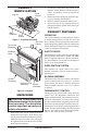
Product Identification Rear Burner Log Set 2. Locate two screws above top corners of the fireplace screen. Remove and discard these screws. Lift fireplace screen up and pull out to remove. 3. Remove protective packaging applied to logs, log base assembly, and fireplace. 4. Remove fireplace hood from carton insert. 5. Check all items for any shipping damage. If damaged, promptly inform dealer where you bought fireplace.
Air For Combustion and Ventilation WARNING: This firebox shall not be installed in a confined space or unusually tight construction unless provisions are provided for adequate combustion and ventilation air. Read the following instructions to insure proper fresh air for this and other fuel-burning appliances in your home. Today’s homes are built more energy efficient than ever. New materials, increased insulation and new construction methods help reduce heat loss in homes.
AIR FOR COMBUSTION AND VENTILATION Continued DETERMINING FRESH-AIR FLOW FOR HEATER LOCATION Determining if You Have a Confined or Unconfined Space Use this work sheet to determine if you have a confined or unconfined space. Space: Includes the room in which you will install heater plus any adjoining rooms with doorless passageways or ventilation grills between the rooms. 1. 2. 3. Determine the volume of the space (length x width x height). Length x Width x Height =__________cu. ft.
AIR FOR COMBUSTION AND VENTILATION Continued Ventilation Air From Inside Building This fresh air would come from an adjoining unconfined space. When ventilating to an adjoining unconfined space, you must provide two permanent openings: one within 12" of the ceiling and one within 12" of the floor on the wall connecting the two spaces (see options 1 and 2, Figure 3). You can also remove door into adjoining room (see option 3, Figure 3). Follow the National Fuel Gas Code, ANSI Z223.1/NFPA 54, Section 5.
Installation Continued WARNING: These models have a three-prong, grounded electrical plug. This plug helps protect you against electrical shock. Only connect plug to a properly grounded, three-prong receptacle. Do not cut or remove the grounding prong from this plug. CAUTION: This fireplace creates warm air currents. These currents move heat to wall surfaces next to fireplace.
Installation Continued 4. Slide one end of adjusting plate/shim in slot on mitered edge of top trim (see Figure 6). 5. Slide other end of adjusting plate/shim in slot on mitered edge of side trim (see Figure 6). 6. While firmly holding edges of trim together, tighten both set screws on the adjusting plate with slotted screwdriver. 7. Repeat steps 1 through 6 for other side. 8. Tighten trim hanging screws (#10 x 6.25 shoulder) into holes in cabinets. Place the assembled trim onto fireplace cabinet.
Installation Continued 5. Route flexible gas line through access hole in hearth base. 6. Center cabinet mantel on hearth base (see Figure 10). Make sure mantel is flush against wall. 7. Break off nailing flanges (see Figure 11) with hammer or pliers. 8. Place cardboard or other protective material on top of hearth base. Carefully set fireplace on protective material, with back of fireplace inside mantel opening. 9.
Installation Continued 1. Frame in rough opening. Use dimensions shown in Figure 13 for the rough opening. If installing in a corner, use dimensions shown in Figure 14 for the rough opening. The height is 33" which is the same as the wall opening above. 2. If using blower, install and properly ground GA3555, three-prong 120 volt electrical outlet, in fireplace. Follow instructions included in kit. 3. Install gas piping into fireplace location.
Installation Continued Note: All Vertical measurements are from top of fireplace opening to bottom of mantel shelf. Mantel Shelf 10" 8" 6" 2 1/2" 21" 19" 16" 13" Minimum NonCombustible Material Figure 16 - Minimum Mantel Clearances for Built-In Installation Installing Gas Piping to Fireplace Location WARNING: This appliance requires a 1/2" NPT (National Pipe Thread) inlet connection to the pressure regulator. WARNING: A qualified service person must connect fireplace to gas supply.
Installation CONNECTING Fireplace to Gas Supply Continued Installation must include an equipment shutoff valve, union and plugged 1/8" NPT tap. Locate NPT tap within reach for test gauge hook up. NPT tap must be upstream from fireplace (see Figure 18). IMPORTANT: Install equipment shutoff valve in an accessible location. The equipment shutoff valve is for turning on or shutting off the gas to the appliance.
Installation Pressure Testing gas Supply Piping system Continued NOTICE: Most building codes do not permit concealed gas connections. A flexible gas line is provided to allow accessibility from the fireplace (see Figure 20). The flexible gas supply line connection to the equipment shutoff valve should be accessible. 4. Attach the flexible gas line to gas supply (see Figure 20). Check tightness of flexible gas line attached to gas regulator of fireplace (see Figure 20). 5.
Installation INSTALLING LOGS Continued Pressure Testing Fireplace Gas Connections 1. Open equipment shutoff valve (see Figure 21, page 15). 2. Open main gas valve located on or near gas meter for natural gas or open propane/LP supply tank valve. 3. Make sure control knob of fireplace is in the OFF position. 4. Check all joints from equipment shutoff valve to gas control valve (see Figures 22 or 23). Apply noncorrosive leak detection fluid to all joints. Bubbles forming show a leak. 5.
Installation Operating Fireplace Continued 7. Install fireplace screen by slipping notches of fireplace screen over screws on front of fireplace (see Figure 26). WARNING: You must operate this fireplace with the fireplace screen in place. Make sure fireplace screen is in place before running fireplace.
OPERATING FIREPLACE Continued LIGHTING INSTRUCTIONS WARNING: You must operate this fireplace with the fireplace screen in place. Make sure fireplace screen is installed before running fireplace. NOTICE: During initial operation of new fireplace, burning logs will give off a paper-burning smell. Orange flame will also be present. Open window to vent smell. Operate fireplace on HI position to burn off odor. This will only last a few hours. 1. STOP! Read the safety information, page 17. 2.
OPERATING FIREPLACE Continued MANUAL LIGHTING PROCEDURE 1. Follow steps 1 through 5 under Lighting Instructions, page 18. 2. Depress control knob and light pilot with match. 3. Keep control knob pressed in for 30 seconds after lighting pilot. After 30 seconds, release control knob. Now follow step 8 under Lighting Instructions, page 18. Note: The pilot flame on natural gas units will have a slight curve, but flame should be blue and have no yellow or orange color.
Inspecting Burners Continued NOTICE: Do not mistake orange flames with yellow tipping. Dirt or other fine particles are burned by fireplace, causing brief patches of orange flame. If front burner flame pattern is incorrect, as shown in Figure 32 on page 19 • turn fireplace off (see To Turn Off Gas to Appliance, page 18) • see Troubleshooting, page 22 Cleaning and Maintenance WARNING: Turn off fireplace and let cool before cleaning.
Cleaning and Maintenance Specifications Continued Ports/ Slots Burner Tube Pilot Assembly Pilot Air Inlet Hole Figure 34 - Pilot Inlet Air Hole LOGS • If you remove logs for cleaning, refer to Installing Logs, pages 16, to properly replace logs. • Replace log(s) if broken or chipped (dime-sized or larger). Model VSGF28NTA • Rating (Variable) 21,000/28,000 Btu/Hr • Type Gas Natural Gas • Ignition Piezo • Pressure Manifold 3.4" W.C. • Inlet Gas Pressure (in. of water) Maximum 10.
Troubleshooting WARNING: Turn off heater and let cool before servicing. Only a qualified service person should service and repair heater. CAUTION: Never use a wire, needle or similar object to clean ODS/pilot. This can damage ODS/pilot unit. Note: All troubleshooting items are listed in order of operation. OBSERVED PROBLEM POSSIBLE CAUSE REMEDY When ignitor button is pressed, there is no spark at ODS/pilot 1. Ignitor electrode not connected to ignitor cable 2. Ignitor cable pinched or wet 1.
Troubleshooting Continued OBSERVED PROBLEM POSSIBLE CAUSE REMEDY ODS/pilot lights but flame goes out when control knob is released 1. Control knob not fully pressed in 2. Control knob not pressed in long enough 1. Press in control knob fully 2. After ODS/pilot lights, keep control knob pressed in 30 seconds 3. Fully open equipment shutoff valve 4. A) Contact local natural or propane/LP gas company 3. Equipment shutoff valve not fully open 4.
Troubleshooting Continued OBSERVED PROBLEM POSSIBLE CAUSE REMEDY Slight smoke or odor during initial operation 1. Residues from manufacturing processes and logs curing 1. Problem will stop after a few hours of operation Moisture/condensation noticed on windows 1. Not enough combustion/ventilation air 1. Refer to Air for Combustion and Ventilation requirements (page 6) Fireplace produces a whistling noise when burners are lit 1. Turning control knob to HI position when burners are cold 2.
Troubleshooting Continued WARNING: If you smell gas Shut off gas supply. Do not try to light any appliance. Do not touch any electrical switch; do not use any phone in your building. Immediately call your gas supplier from a neighbor’s phone. Follow the gas supplier’s instructions. • If you cannot reach your gas supplier, call the fire department. • • • • IMPORTANT: Operating fireplace where impurities in air exist may create odors.
Replacement Parts Note: Use only original replacement parts. This will protect your warranty coverage for parts replaced under warranty. Parts Under Warranty Accessories Notice: All accessories may not be available for all fireplace models. Contact authorized dealers of this product. If they can’t supply original replacement part(s), call DESA Heating Products’ Technical Service Department at 1-866-672-6040.
Accessories Perimeter TRIM ACCESSORY Continued CLEANING KIT - GCK All Models. Your vent-free gas appliance requires regular cleaning and maintenance to prevent performance problems. This kit gives you the tools and instructions to make it easy to clean all critical areas of your appliance. Firebox Brick Liner - G8005 Series (Not Shown) All Models. Ceramic fiber firebox liner adds the look of real brick.
Illustrated Parts Breakdown Models VSGF26NTF, VSGF26PTF 1d 1f 1c 1b 1a 7 1e 8 6 4 5 26 10 23 18 9 11 13 2 3 17 15 24 12 18 16 25 21 12 22 14 19 28 20 www.desatech.
Parts List 1a 1b 1c 1d 1e 1f 2 3 4 5 6 7 8 9 10 11 12 13 14 15 16 17 18 19 20 21 22 23 24 25 26 DESCRIPTION 113621-07 113621-08 113621-09 113621-10 113621-19 113621-12 M11084-38 098304-01 107486-01 107485-01 098249-01 112713-01 112465-02 112466-02 112705-03 098271-10 ** 098867-10 098867-09 101004-01 101004-04 102845-01 101382-01 099387-09 112708-06 097809-02 099211-01 098544-01 101329-14 101329-20 101381-01 101004-15 101004-14 101628-03 901063-01 M11084 Front Log Right Front Log Left Middle Right Log Mi
ILLUSTRATED PARTS BREAKDOWN Models VSGF28PTF and VSGF28NRF 17 7 1 6 9 2 16 12 4 8 16 3 11 11 14 24 16 16 16 19 24 11 15 5 21 16 7 10 18 16 16 26 10 22 13 20 25 24 30 www.desatech.
PARTS LIST Models VSGF28PTF and VSGF28NRF This list contains replaceable parts used in your firebox. When ordering parts, follow the instructions listed under Replacement Parts on page 26 of this manual. KEY NO. PART NO.
Warranty Information KEEP THIS WARRANTY Model Serial No. Date Purchased Always specify model and serial numbers when communicating with the factory. We reserve the right to amend these specifications at any time without notice. The only warranty applicable is our standard written warranty. We make no other warranty, expressed or implied.