
UnVenTed (VenT-Free) Gas FirePlace sysTem VsGF28nTF, VsGF28PTF
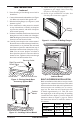
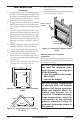
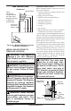
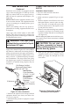
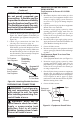
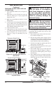
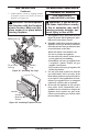
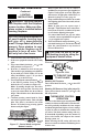
Table Of Contents
- Safety Information
- Local Codes
- Product Identification
- Unpacking
- Product Features
- Air For Combustion and Ventilation
- Installation
- Operating Fireplace
- Inspecting Burners
- Cleaning and Maintenance
- Wiring Diagram
- Specifications
- Troubleshooting
- Replacement Parts
- Technical Service
- Service Hints
- Accessories
- Illustrated Parts Breakdown and Parts List
- Warranty Information
www.desatech.com
119303-01A
11
INSTALLATION
Continued
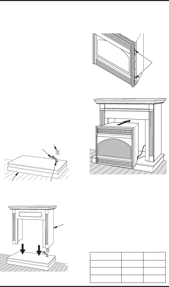
Figure 9 - Placing Hearth Base
Accessory Against Wall
Electrical Outlet
Hearth Base
Rigid Pipe and Gas
Shutoff Valve
Gas Line Access Hole
Figure 10 - Installing Cabinet Mantel
Cabinet
Mantel
Figure 11 - Location of Nailing Flanges
Nailing
Flanges
5. Route exible gas line through access hole in
hearth base.
6. Center cabinet mantel on hearth base (see Figure
10). Make sure mantel is ush against wall.
7. Break off nailing anges (see Figure 11) with
hammer or pliers.
8. Place cardboard or other protective material
on top of hearth base. Carefully set replace
on protective material, with back of replace
inside mantel opening.
9. If blower is installed, route blower electrical cord
through access holes in either side of replace.
Note: Bushing may be moved if necessary. Plug
electrical cord into electrical outlet.
10. Carefully insert replace into cabinet mantel.
Be careful not to scratch or damage hearth base,
cabinet mantel, or any laminate trim on hearth
base. Remove protective material from top of
hearth base and from front of replace (if any).
Note: You can secure replace to hearth or
oor. Open lower louver. Locate screw holes in
bottom of base. Tighten wood screws through
these holes and into hearth or oor.
11. Attach exible gas line from replace gas
regulator to gas supply. See Connecting
Fireplace to Gas Supply, page 14.
12. Check all gas connections for leaks. See
Checking Gas Connections, page 15.
32
3
/8" 33"
Front Width 34
5
/16" 35
1
/2"
16
11
/16" 17
3
/4"
BUILT-IN FIREBOX INSTALLATION
Built-in installation of this rebox involves install-
ing rebox into a framed-in enclosure. This makes
the front of rebox ush with wall. Optional brass
trim accessories are available (see Accessories,
page 20). The brass trim will extend past sides
of rebox approximately 1/2". This will cover
the rough edges of the wall opening. If installing
a mantel above the rebox, you must follow the
clearances shown in Figure 6, page 10. Follow
the instructions below to install the rebox in
this manner.
Figure 12 - Inserting Fireplace into
Cabinet Mantel