VENTED DECORATIVE NATURAL GAS LOGS OWNER’S OPERATION AND INSTALLATION MANUAL ANSI Z21.
TABLE OF CONTENTS Safety................................................................... 2 Local Codes......................................................... 4 Unpacking............................................................ 4 Product Identification............................................ 5 Optional Product Features................................... 5 Installation............................................................ 5 Operation...........................................................
Safety Continued Natural Gas: Natural gas is odorless. An odor- making agent is added to the gas. The odor helps you detect a gas leak. However, the odor added to the gas can fade. Gas may be present even though no odor exists. Make certain you read and understand all warnings. Keep this manual for reference. It is your guide to safe and proper operation of this log set. Appliance assembly becomes very hot when in use. Keep children and adults away from hot surface to avoid burns or clothing ignition.
Safety Continued 4. This log set is designed to be smokeless. If logs ever appear to smoke, turn off appliance and call a qualified service person. Note: During initial operation, slight smoking could occur due to log curing and the burning of manufacturing residues. You may wish to add more ventilation by opening a window. 5. To reduce the creation of soot, follow the instructions in Cleaning and Maintenance, page 15. 6.
Product Identification Grate Steps Grate Hearth Kit Model____________________ Serial Number______________________ Log Set Model______________________ Burner Pan Burner Clamp Burner Inlet Fitting Burner Manifold Figure 1 - Product Identification (Dual Burner Shown) Optional Product Features ON/OFF Safety Valve/Pilot kit and Propane/lp conversion An optional valve/safety pilot kit with a piezo ignitor is available for this appliance. This system requires no matches, batteries, or other sources to light.
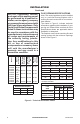
installation Continued Btu/Hr Input Propane/LP Gas Minimum Vent Opening 18" 50,000 Single 40,000 8" dia. VVSR24 FVSR24 24" 60,000 Single 50,000 8" dia. Burner Description VVSR18 FVSR18 Model Btu/Hr Input Natural Gas NOTICE: Installation, service, and repair of this appliance must be performed by a qualified installer, service agency, company or gas supplier experienced with this type of gas appliance.
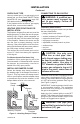
INSTALLATION Continued CHECK GAS TYPE CONNECTING TO GAS SUPPLY Use only natural gas. If your gas supply is not natural gas, you must install ON/OFF Safety Valve/Pilot Kit (see Accessories, page 24). Call dealer where you bought log set. If the fireplace does not have a gas supply shutoff valve, one must be installed. VENTING SPECIFICATIONS FOR INSTALLATION The fireplace chimney flue and vent must be drafting properly.
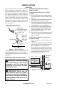
INSTALLATION Continued We recommend that you install a sediment trap in supply line as shown in Figure 4. Locate sediment trap where it is within reach for cleaning. Install in piping system between fuel supply and heater. Locate sediment trap where trapped matter is not likely to freeze. A sediment trap traps moisture and contaminants. This keeps them from going into log set controls. If sediment trap is not installed or is installed wrong, log set may not run properly.
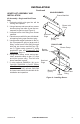
INSTALLATION Continued Hearth kit assembly and Installation Kit Assembly - Single and Dual Flame Only 1. Determine which side gas line will be coming into fireplace. 2. Using a hammer and screw driver, remove knockout plug from side of pan that corresponds to gas line (see Figure 6). 3. Unscrew burner inlet fitting from burner manifold. 4. Place burner manifold in pan with threaded opening facing open knockout plug. 5.
INSTALLATION Continued Installation and Gas Connection 1. Place burner pan assembly in center of fireplace floor. Make sure front of pan faces forward. 2. Thread gas supply fitting to fireplace gas supply pipe. Use thread sealant. 3. Install adapter fitting onto burner inlet fitting using thread sealant on male threads of burner inlet fitting (see Figure 7). Adjust to most convenient position. 4. Install gas connector tube to gas supply fitting. Carefully shape tube to attach to adapter fitting.
INSTALLATION Continued 6. Install gas connector tube to gas supply fitting. Carefully shape tube to attach to adapter fitting. Be careful not to cause kinks in tube. 7. Test for leaks following instructions under Testing Burner for Leaks, page 12. 8. Retighten and adjust location of gas control as necessary. Gas control should be level, with control rod to front. 9. Install cover to burner pan using screws provided. 10. Install thermocouple, pilot, and ignitor onto valve cover as shown in Figure 11.
INSTALLATION Continued Changing Pilot Orifice The pilot is provided with a natural gas orifice installed. For propane/LP gas you must remove it and replace it with an propane/LP orifice. The accessory hardware kit contains an propane/LP orifice with a red stripe for converting pilot. 1. Gently loosen and remove pilot line connection from bracket (see Figure 14). 2. Replace injector (see Figure 14) with propane/LP pilot injector with red stripe. 3. Replace and tighten pilot line to bracket. 4.
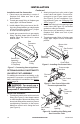
INSTALLATION Continued 5. Place smaller top logs onto bottom logs (see Figure 17). Leave as much open space between logs as possible to minimize flame impingement and sooting. Note: Logs may chip if they are handled roughly or if hit together while being placed. Figure 17 - Placement of Top Logs Logs (Number and style may vary) Figure 16 - Installing Front and Back Logs (Number and style may vary) 124183-01B www.desatech.
Operation FOR YOUR SAFETY READ BEFORE LIGHTING Gas shutoff valve operation WARNING: Keep flue open when operating unit. Flame Adjustment Adjust the flame ON/OFF by turning gas shutoff valve counterclockwise to open or clockwise to close, as necessary. WARNING: If you do not follow these instructions exactly, a fire or explosion may result causing property damage, personal injury or loss of life. BEFORE LIGHTING smell all around the appliance area for gas.
OPERATIon Continued 9. ON ON OFF FROM "PILOT" POSITION SLIGHT PUSH TO TURN OFF PULL PUSH TO LIGHT FROM "PILOT" POSITION SLIGHT PUSH TO TURN OFF PULL PUSH TO LIGHT OFF On Off OFF 8. Control Knob Pilot ON 7. Ignitor FROM "PILOT" POSITION SLIGHT PUSH TO TURN OFF PULL PUSH TO LIGHT 6. Note: You may be running this log set for the first time after hooking up to gas supply. If so, the control knob may need to be pressed in for 30 seconds. This will allow air to bleed from the gas system.
Troubleshooting WARNING: Turn off log set and let cool before servicing. Only a qualified service person should service and repair log set. Note: All troubleshooting items are listed in order of operation. OBSERVED PROBLEM POSSIBLE CAUSE Log set is smoking/sooting excessively (Note: It is natural and unavoidable for vented gas log sets to produce moderate levels of carbon (soot) where flames contact the logs. This is especially true with propane/LP gas.) 1. Poor fuel quality REMEDY 1.
troubleshooting Continued OBSERVED PROBLEM POSSIBLE CAUSE When ignitor button is pressed, 1. Gas supply turned off or equipment shutoff valve there is spark at pilot but no closed ignition (GA9050A-1 Only) 2. Control knob not in PILOT position 3. Control knob not pressed in while in PILOT position 4. Air in gas lines when installed REMEDY 1. Turn on gas supply or open equipment shutoff valve 2. Turn control knob to PILOT position 3. Press in control knob while in PILOT position 4.
troubleshooting Continued WARNING: If you smell gas • Shut off gas supply. • Do not try to light any appliance. • Do not touch any electrical switch; do not use any phone in your building. • Immediately call your gas supplier from a neighbor’s phone. Follow the gas supplier’s instructions. • If you cannot reach your gas supplier, call the fire department. IMPORTANT: Operating log set where impurities in air exist may create odors.
Service Hints Technical Service When Gas Pressure is Too Low • pilot will not stay lit • burners will have delayed ignition • heater will not produce specified heat • propane/LP gas supply may be low You may feel your gas pressure is too low. If so, contact your local propane/LP or natural gas supplier. You may have further questions about installation, operation, or troubleshooting. If so, contact DESA Heating, LLC at 1-866-672-6040.
Parts burner models VVSR18, FVSR18, VVSR24, FVSR24, VVDR18, FVDR18, VVDR24, FVDR24, VVDR30 AND FVDR30 This list contains replaceable parts used in your log set. When ordering parts, follow the instructions listed under Replacement Parts on page 19 of this manual. 9 9 10 7 12 5 11 5 1 6 8 4 3 2 13 KEY VVSR18 NO.
PARTS 7 Log Set Models VSLR18, VSLR24, VDLCR18, VDLCR24 and VDLCR30 This list contains replaceable parts used in your log set. When ordering parts, follow the instructions listed under Replacement Parts on page 19 of this manual.
PARTS 4 Log Set Models FSLR18, FSLR24, FDLCR18, FDLCR24 and FDLCR30 This list contains replaceable parts used in your log set. When ordering parts, follow the instructions listed under Replacement Parts on page 19 of this manual.
PARTS Log Set Models FA18, FA24 and FA30 This list contains replaceable parts used in your log set. When ordering parts, follow the instructions listed under Replacement Parts on page 19 of this manual. 3 2 1 4 5 6 124183-01B Bottom Log (FA-17) Top Log (VCR-12) Top Log (CPR-13S) Bottom Log (FA-19) Bottom Log (FA-9) Bottom Log (FA-12) 118039-01 901121-01 901096-01 118040-01 118038-01 118041-01 www.desatech.com FA3 0 DESCRIPTION 1 2 3 4 5 6 FA2 4 KEY NO. PART NO.
Accessories Purchase these accessories from your local dealer. If they can not supply these accessories call DESA Heating, LLC at 1-866-672-6040 for information. You can also write to the address listed on the back page of this manual. Individual Round Log - GA9450A For decorative purposes only. Not to be used as additional logs on unit. Individual Split Log - GA9550A For decorative purposes only. Not to be used as additional logs on unit.
NOTES _____________________________________________________ ______________________________________________________ ______________________________________________________ ______________________________________________________ ______________________________________________________ ______________________________________________________ ______________________________________________________ ______________________________________________________ ______________________________________________________ ___________
NOTES _____________________________________________________ ______________________________________________________ ______________________________________________________ ______________________________________________________ ______________________________________________________ ______________________________________________________ ______________________________________________________ ______________________________________________________ ______________________________________________________ ___________
NOTES _____________________________________________________ ______________________________________________________ ______________________________________________________ ______________________________________________________ ______________________________________________________ ______________________________________________________ ______________________________________________________ ______________________________________________________ ______________________________________________________ ___________
Warranty KEEP THIS WARRANTY Model (located on product or identification tag)______________________________ Serial No. (located on product or identification tag)___________________________ Date Purchased ___________________________ Keep receipt for warranty verification.