
OWNER'S OPERATION AND INSTALLATION MANUAL UNVENTED (VENT-FREE) GAS LOG HEATER VYM27NRPR, FVFM27NR/PR

110398-01A
For more information, visit www.desatech.com
For more information, visit www.desatech.com
13
13
O
F
F
P
I
L
O
T
O
N
H
I
L
O
O
F
F
P
I
L
O
T
O
N
H
I
L
O
INSTALLATION
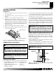
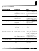
Checking Gas Connections (Cont.)
Installing Logs
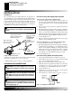
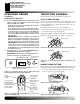
Figure 17 - Checking Gas Joints for Propane/LP Gas
Control Valve Location
Propane/LP
Supply Tank
Equipment Shutoff Valve
Figure 16 - Checking Gas Joints for Natural Gas
Gas Meter
Equipment Shutoff Valve
Control Valve Location
INSTALLATION
Continued
WARNING: Failure to position the parts in accor-
dance with these diagrams or failure to use only parts
specifically approved with this heater may result in
property damage or personal injury.
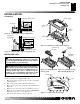
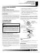
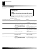
INSTALLING LOGS
It is very important to install the logs exactly as instructed. Do not
modify logs. Only use logs supplied with heater.
1. Place front log (#1) and rear log (#2) on grate to fit as illus-
trated in Figure 18.
2. Place center insert log (#3) as illustrated in Figure 19.
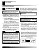
3. Place top left log (#4) and top right log (#5) as illustrated in
Figure 20.
4. Make sure open areas of logs line up with burner ports (see
Figure 21). Logs will fit securely on chassis.
IMPORTANT:
Make sure log does not cover any burner ports.
5. Place lava rock around base of heater if desired.
CAUTION: After installation and periodically there-
after, check to ensure that no flame comes in contact
with any log. With the heater set to HIGH, check to see
if flames contact any log. If so, reposition logs ac-
cording to the log installation instructions in this
manual. Flames contacting logs will create soot.
Figure 18 - Installing Front (#1) and Rear (#2) Logs
Rear Log (#2)
Burner
Chassis
Grate
Burner
Port
Front Log
(#1)
Figure 19 - Installing Center
Insert Log (#3)
Logs
Burner Ports
Figure 20 - Installing Top Left
(#4) and Top Right (#5) Logs
Figure 21 - Installing Log Set (Top View)
Center Insert
Log (#3)
O
F
F
P
I
L
O
T
O
N
H
I
L
O
Top Left
Log (#4)
Top Right
Log (#5)