UNVENTED (VENT-FREE) GAS LOG HEATER OWNER’S OPERATION AND INSTALLATION MANUAL PFS ® US Models VF-18N-MHD, VF-18P-MHD, VF-24N-MHD and VF-24P-MHD WARNING: If the information in this manual is not followed exactly, a fire or explosion may result causing property damage, personal injury or loss of life. — Do not store or use gasoline or other flammable vapors and liquids in the vicinity of this or any other appliance. — WHAT TO DO IF YOU SMELL GAS • Do not try to light any appliance.
TABLE OF CONTENTS Safety................................................................... 2 Unpacking............................................................ 4 Product Identification............................................ 5 Local Codes......................................................... 5 Product Features.................................................. 5 Air For Combustion and Ventilation...................... 5 Installation............................................................
safety Continued WARNING: This product contains and/or generates chemicals known to the State of California to cause cancer or birth defects or other reproductive harm. IMPORTANT: Read this owner’s manual carefully and completely before trying to assemble, operate or service this heater. Improper use of this heater can cause serious injury or death from burns, fire, explosion, electrical shock and carbon monoxide poisoning.
safety Continued 1. This appliance is only for use with the type of gas indicated on the rating plate. This appliance is not convertible for use with other gases. 2. Do not place propane/LP supply tank(s) inside any structure. Locate propane/LP supply tank(s) outdoors (propane/LP units only). 3. If you smell gas • shut off gas supply • do not try to light any appliance • do not touch any electrical switch; do not use any phone in your building • immediately call your gas supplier from a neighbor’s phone.
Product Identification Log Set Assembly Control Valve with Remote Receiver Module Hand-Held Remote Control Chassis Assembly Figure 1 - Product Identification Local Codes Install and use heater with care. Follow all local codes. In the absence of local codes, use the latest edition of The National Fuel Gas Code ANSI Z223.1/NFPA 54*. *Available from: American National Standards Institute, Inc. 1430 Broadway New York, NY 10018 National Fire Protection Association, Inc.
air for combustion and ventilation Continued While it is good to make your home energy efficient, your home needs to breathe. Fresh air must enter your home. All fuel-burning appliances need fresh air for proper combustion and ventilation. Exhaust fans, fireplaces, clothes dryers and fuel burning appliances draw air from the house to operate. You must provide adequate fresh air for these appliances. This will insure proper venting of vented fuel-burning appliances.
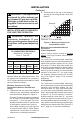
Air for combustion and ventilation Continued Example: 40,000 Gas water heater _ __________Btu/Hr 33,000 Vent-free fireplace+ _ __________Btu/Hr 73,000 Total= _ __________Btu/Hr 4. Compare the maximum Btu/Hr the space can support with the actual amount of Btu/Hr used.
Installation NOTICE: This heater is intended for use as supplemental heat. Use this heater along with your primary heating system. Do not install this heater as your primary heat source. If you have a central heating system, you may run system’s circulating blower while using heater. This will help circulate the heat throughout the house. In the event of a power outage, you can use this heater as your primary heat source. WARNING: A qualified service person must install heater. Follow all local codes.
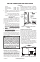
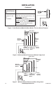
Installation Continued WARNING: This appliance is equipped for either natural gas or propane/LP gas but not both. Gas type is indicated on the rating plate. Field conversion is not permitted. B. Clearances from the top of the fireplace opening to the ceiling should not be less than 42". Example installation and clearances for vent-free operation WARNING: Maintain the minimum clearances. If you can, provide greater clearances from floor, ceiling and adjoining wall.
INSTALLATION Continued Noncombustible Material Distance (A) 12" or more Between 8" and 12" Less than 8 Requirements for Safe Installation Noncombustible material OK Install fire place hood accessory ( see Accessories, page 25). Noncombustible material must be extended to at least 8". See Between 8" and 12", above. If you cannot extend material, you must operate heater with flue damper open. Figure 5 - Heat Resistant Material (Slate, Marble, Tile, etc.
INSTALLATION Continued Mantel Clearances In addition to meeting noncombustible material clearances, you must also meet required clearances between fireplace openings and mantel shelf on each side of the fireplace. If you do not meet the clearances listed below, you will need a hood.
INSTALLATION Continued Installation Items Needed • control cover kit (provided with heater) • approved flexible gas hose (if allowed by local codes) • sealant (resistant to propane/LP gas, not provided) 1. Apply pipe joint sealant lightly to male threads of gas fitting (not provided). Connect approved flexible gas hose to inlet side of gas control (see Figure 10). IMPORTANT: Hold gas fitting with wrench when connecting flexible gas hose. 2. Position heater assembly in fireplace. 3. Connect to gas supply.
INSTALLATION Continued Installation must include an equipment shutoff valve, union and plugged 1/8" NPT tap. Locate NPT tap within reach for test gauge hook up. NPT tap must be upstream from heater (see Figure 12). IMPORTANT: Install equipment shutoff valve in an accessible location. The equipment shutoff valve is for turning on or shutting off the gas to the appliance. Check your building codes for any special requirements for locating equipment shutoff valve to fireplaces.
Installation Continued 4. Check all joints of gas supply piping system. Apply noncorrosive leak detection fluid to all joints. Bubbles forming show a leak. 5. Correct all leaks at once. 6. Reconnect heater and equipment shutoff valve to gas supply. Check reconnected fittings for leaks. Test Pressures Equal To or Less Than 1/2 PSIG (14" W.C.) 1. Close equipment shutoff valve (see Figure 13). 2.
Installation Continued 4. Add lava rock and small decorative logs around base of heater if desired (see Figure 17). You may place lava rock and log pieces up to flat burner. DO NOT place rock or logs on front burner or on logs. Placing any material on unit other than ember material on front burner may result in production of carbon monoxide or soot. WARNING: Do not operate unit without ember material correctly in place as shown in Figure 16, page 14. Do NOT place ember material anywhere else on the unit.
Operation Continued Remote lighting instructions WARNING: • If fireplace has glass doors, never operate this heater with glass doors closed. If you operate heater with doors closed, heat buildup inside fireplace will cause glass to burst. Make sure there are no obstructions across openings of fireplace. • You must operate this heater with a fireplace screen in place. Make sure fireplace screen is closed before running heater.
Operation Continued Shut Off Procedure To save battery power, press to turn main gas to pilot gas. Press the OFF button to shut off the device including pilot flame. The device can be shut off with ON/OFF switch, thus disabling remote hand set. Setting Display ( °C/24h and °F /12h) until display Press and hold OFF and changes from °F (and 12 hour clock) to °C (and 24 hour clock) or vice versa. Setting The Time • After connecting battery or by simultaneand the display will ously pressing start to flash.
Operation Continued MANUAL LIGHTING Procedure WARNING: Manual lighting must be performed by a qualified service person. 11. Turn motor knob to adjust flame. Knob has a slipping clutch that allows manual flame height adjustment as well as adjustment to pilot gas. Thermocouple Pilot Burner The system has a "MANUAL OVERRIDE" feature that allows you to light with a match. Lighting with a Match 1. STOP! Read the safety information on page 15 . 2. Make sure equipment shutoff valve is fully open. 3.
Inspecting Burners Check pilot flame pattern and burner flame patterns often. PILOT FLAME PATTERN Figure 21 shows a correct pilot flame pattern. Figure 22 shows an incorrect pilot flame pattern. The incorrect pilot flame is not touching the thermocouple. When the thermocouple cools, the heater will shut down.
Cleaning and Maintenance WARNING: Turn off heater and let cool before cleaning. CAUTION: You must keep control areas, burner and circulating air passageways of heater clean. Inspect these areas of heater before each use. Have heater inspected yearly by a qualified service person. Heater may need more frequent cleaning due to excessive lint from carpeting, bedding material, pet hair, etc. 2 . Remove screws from left and right side of front log assembly to remove from base assembly (see Figure 25). 3.
Troubleshooting WARNING: Turn off heater and let cool before servicing. Only a qualified service person should service and repair heater. CAUTION: Never use a wire, needle or similar object to clean ODS/pilot. This can damage ODS/pilot unit. Note: All troubleshooting items are listed in order of operation. OBSERVED PROBLEM POSSIBLE CAUSE REMEDY When and are pressed at the same time, there is no spark at ODS/ pilot 1. Switch in OFF position (module gives long steady beep) 2.
troubleshooting Continued OBSERVED PROBLEM POSSIBLE CAUSE REMEDY Delayed ignition burner 1. Manifold pressure is too low 2. Burner orifice(s) clogged 1. Contact local natural or propane/LP gas company 2. Clean burner (see Cleaning and Maintenance, page 20) or replace burner orifice Burner backfiring during combustion 1. Burner orifice is clogged or damaged 1. Clean burner (see Cleaning and Maintenance, page 20) or replace burner orifice 2. Replace damaged burner 3. Replace gas regulator 2.
troubleshooting Continued WARNING: If you smell gas • Shut off gas supply. • Do not try to light any appliance. • Do not touch any electrical switch; do not use any phone in your building. • Immediately call your gas supplier from a neighbor’s phone. Follow the gas supplier’s instructions. • If you cannot reach your gas supplier, call the fire department. IMPORTANT: Operating heater where impurities in air exist may create odors.
troubleshooting Continued Identifying error signals from receiver OBSERVED PROBLEM POSSIBLE CAUSE REMEDY Long signals (0.8 second tone, 0.2 second break) during ignition Battery nearly down. (When signal appears the first time approximately 10 ignitions left) Replace battery 5 second continuous tone Cable is not connected, ON/OFF switch is in OFF position Connect cables 5 short signals (8.2 second tone, 0.2 second break) Ignition not successful, possible air in supply line Switch to ON.
Replacement Parts Note: Use only original replacement parts. This will protect your warranty coverage for parts replaced under warranty. Contact authorized dealers of this product. If they can’t supply original replacement part(s), call FMI PRODUCTS, LLC at 1-866-328-4537. When calling, have ready: • your name • your address • model and serial numbers of your heater • how heater was malfunctioning • purchase date Usually, we will ask you to return the part to the factory.
Parts Models VF-18N-MHD, VF-18P-MHD, VF-24N-MHD and VF-24P-MHD 30 24 22 27 25 22 32 28 29 20 29 1 28 15 7 24 27 15 3 15 21 15 13 14 31 15 15 15 11 19 4 23 26 6 17 31 34 12 9 16 16 18 10 15 15 15 31 15 15 5 8 2 33 15 26 www.fmiproducts.
Parts This list contains replaceable parts used in your heater. When ordering parts, follow the instructions listed under Replacement Parts on page 25 of this manual. PART NUMBER KEY NO.
Warranty KEEP THIS WARRANTY Model (located on product or identification tag)______________________________ Serial No. (located on product or identification tag)___________________________ Date Purchased ___________________________ Keep receipt for warranty verification.