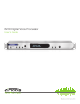
6200 Digital Voice Processor User’s Guide
Safety 6408 216th Street SW | Mountlake Terrace, WA 98043 USA T +1.425.778.7728 F +1.425.778.7727 | www.SymetrixAudio.
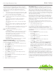
Safety 6200 Digital Broadcast Delay What Ships in the Box • A 6200 hardware device. • A 6200 Designer CD-ROM (Windows). • A detachable power cord. • This User’s Guide. What You Need to Provide (for optional PC GUI control only) Important Safety Instructions ! @ # $ % • A Windows PC with 300MHz or higher Pentium and: • WIN 98SE, ME, 2000 or XP. • 10-15 MB free storage space. • 1024x768 graphics capability. • 16-bit or higher colors. ^ & • CD-ROM drive or Internet connection.
Introduction User’s Guide Introduction The AirTools 6200 Digital Voice Processor is designed to meet the increasingly sophisticated needs of broadcasters operating in both analog and digital realms featuring an optimum mix of signal processing modules and control features. The modules include: highpass, lowpass, and shelving filters, de-esser, downward expander, comp-limiter/AGC-leveler, 4-band parametric EQ and voice symmetry.
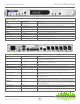
Front and Rear Panel 6200 Digital Broadcast Delay FRONT PANEL ITEM DESCRIPTION DETAILS BYPASS Momentary button Toggles DSP bypass state on top level menus. Toggles DSP module bypass state on individual DSP module menus. PREV / EXIT Momentary button Moves to the previous menu item or exits to the top of the menu tree. NEXT / ENTER Momentary button Moves to the next menu item or enters a menu tree. HOME Momentary button Returns to the “HOME” top-level menu.
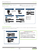
Wiring Reference User’s Guide Balanced Connections NOTE: In the case of an XLR connector, the Female attaches to an output, while the Male attaches to an input. Any of these connectors can appear on either side of a balanced connection. Euroblock [balanced] Terminal Strip [balanced] Tip = (+) Plus Ring = (–) Minus Sleeve = Ground NOTE: Detachable Euroblock and Terminal Strip connectors are designed for use with bare wire. Do not tin stranded wires before inserting them into the connectors.
Wiring Reference 6200 Digital Broadcast Delay Unbalanced Connections: In this example, the unbalanced connector is sending signal to a balanced connector. When wiring this connection, use a shielded twisted pair cable. The balanced side wires the same as a standard, balanced connection. On the unbalanced side, you wire the white (minus) wire together with the ground. This provides some common mode rejection at the balanced input.
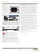
Basic Setup User’s Guide Basic Setup PHANTOM POWER (if required - skip this section if using a dynamic mic which does not require phantom power): All condenser microphones require some kind of electrical power. This power may be supplied by internal batteries, an external power supply that is connected to the microphone by a special multiwire cable, or through a standard microphone cable by “phantom” or “T system” powering.
Basic Setup 6200 Digital Broadcast Delay MIC PREAMP GAIN: Coarse preamp gain for each channel is set in each channel’s setup menu. Fine gain is set within each channel’s program menu. Separating the gain settings like this allows for coarse gain (2 x line level settings and 2 x mic level settings) to be set as a global parameter corresponding to the physical device(s) connected to the 6200’s input(s). The coarse gain setting is not stored in the preset programs.
Basic Setup User’s Guide To set the fine preamp gain (for Channel 1): output. When enabled, the module processes the signal. 1. Press the HOME button to ensure that we are starting from the top. 2. Press the NEXT button once, the display should read “Section to Edit, - Channel 1 Menu -“. High Pass Frequency - Determines the cut-off frequency of the filter. All frequencies below this will be progressively attenuated. Technically, this frequency is the “3 dB down point”, i.e.
Basic Setup 6200 Digital Broadcast Delay Shelving Frequency - Determines where the boost or cut takes place. For low shelf filters, all frequencies below this will be affected. For high shelf filters, all frequencies above this will be affected. Technically, the indicated frequency is the point where the filter has reached half of its specified dB gain. For example, for +6 dB boost with a 1 kHz frequency, the signal is boosted by +3 dB at 1 kHz.
Basic Setup User’s Guide Programs AGC Goal - The desired output signal level to maintain. (Effective in AGC mode only). The 6200 features 256 memory locations in which mono or stereo programs may be stored. If a program is mono, it can be loaded onto or saved from either Channel 1 or Channel 2 independently. A stereo program stores information for both channels simultaneously. Compressor Threshold - This parameter is disabled in AGC mode. Compressor Ratio - This parameter is disabled in AGC mode.
Basic Setup 6200 Digital Broadcast Delay Loading a Program Use this process to load a program you have previously saved. 1. 2. Press briefly the LOAD 1/SAVE 1 button once. The screen will read “Load Mono Pgm 1?” and the name of the program currently stored in this location will readout on the line below. NOTE: If the program in the selected memory location is a stereo program, the text will read “Load Stereo Pgm 1?” instead.
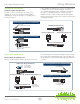
Bypass and Analog Control Inputs User’s Guide Bypass Analog Control Inputs The 6200 has two bypass modes - software (DSP) and hardware (relay). The DSP (SW) bypass can be invoked a number of ways. The hardware (HW) bypass is only accessible via contact closure wired to a rear panel euroblock connector. The 6200 features two analog control inputs which provide real-time control of up to two parameters per port using standard 10k Ohm linear potentiometers. The figure right shows the connections.
Digital AES Out 6200 Digital Broadcast Delay Digital (AES) Out The 6200 features two AES format digital outputs each of which can transmit a combination of channel 1 or channel 2’s content or each channel’s content exclusively. Additionally, a HomerLink jack is provided as a rear panel real estate sensitive means of providing AES/EBU input as well as outputs on a single CAT-5 connection.
AES Input and TC89 and TC90 Timecode In AES Input User’s Guide 6200 HomerLink Pinout HomerLink is a data bus format designed by Symetrix which allows 4 mono bidirectional AES-3 digital audio channels to be transmitted between devices up to 100 meters apart over standard CAT-5 cable. HomerLink outputs (Pins 1, 2, 4 and 5) are exact copies of the AES OUT XLR jacks on the rear of the 6200.
Enabling Network Time Polling 6200 Digital Broadcast Delay Entering the Time Server IP Address and Enabling Network Time Polling 1. Press the HOME button to ensure that we are starting from the top. 2. Press the NEXT button once. 3. Turn the ADJUST knob clockwise until the display reads “Section to Edit, Setup Menu -”. 4. Press the NEXT button once. 5. Turn the ADJUST knob clockwise until the display reads “- Setup Menu -, -- Date and Time --”. 6.
6200 Designer Installation User’s Guide 6200 Designer Installation USB Connection and Driver Installation The 6200 Designer software provides real-time control and a simple drag ‘n drop, point ‘n click configuration interface to the 6200 from a Windows 98/2000/XP PC environment. When you install the 6200 Designer software, a USB driver for the 6200 is also installed into the 6200 Designer program directory.
6200 Designer Installation 6200 Digital Broadcast Delay 7. Now, click the Next button. In the next dialog, choose the option “Search for the best driver in these locations” and check the sub-option “Include this location in the search:”. 8. Windows will install and configure the driver. Then click the Browse button and navigate to the 6200 Designer USB Driver directory (typically “C:\Program Files\Symetrix\6200 Designer\ USB Driver\”).
Alternate Communications Connections Alternate Communications Connections User’s Guide baud rate is required, turn the ADJUST knob to select a another rate. In addition to USB, the 6200 Designer application can communicate with the 6200 hardware via RS-232 or Ethernet. 7. RS-232 Since RS-485 is a multi-drop bus, each unit on the bus must have some unique ID. The 6200 “Unit Number” is this unique ID.
Alternate Communications Connections 6200 Digital Broadcast Delay Example Network: 6200 IP: 10.0.0.2 SM: 255.255.0.0 GW: 10.0.0.1 6. IP: 10.0.0.3 SM: 255.255.0.0 GW: 10.0.0.1 Press OK to save and “Close” to exit out of the “Local Area Connection Properties”. For more information about configuring the host computer, visit www.microsoft.com. Ethernet Setting the 6200’s IP Address: 1. Press the HOME button to ensure that we are starting from the top. 2. Press the NEXT button once. 3.
Alternate Connections • Appendix A Appendix A: Mic Level Output Setting the 6200’s Gateway IP Address: 1. Press the HOME button to ensure that we are starting from the top. 2. Press the NEXT button once. 3. Turn the ADJUST knob clockwise until the display reads “Section to Edit, - Setup Menu -”. 4. Press the NEXT button once. 5. Turn the ADJUST knob clockwise until the display reads “- Setup Menu -, -- Communication --”. 6.
Home CH1:(Program Name) Ch2:(Program Name) > --------------------------------> -------------------------------------------------------> 23 -> High Pass Frequency 16Hz to 19.7kHz -> > HP Filter Slope 6, 12, 12 Peak, 18, 18 Peak, 24 or 24 dB/OCT Peak > Parametric 1 (2-4 same) > De-esser Gentle, Normal, Aggressive > High Pass Filter > AES Assignment > Communication > Network Time Polling > Daylight Savings Disabled, Enabled Disabled, Enabled > Expander > Time Server IP xxx.xxx.xxx.
> Device Name Continued from previous page -----> 6408 216th Street SW | Mountlake Terrace, WA 98043 USA T +1.425.778.7728 F +1.425.778.7727 | www.SymetrixAudio.com > Subnet Mask xxx.xxx.xxx.xxx > 24 > Program Name 20 Characters > Date - Year 2000 to 2099 > > > > > Expander Release 1.0 ms to 5.8 s > Compressor Knee Hard, Soft > Compressor Release 1.0 ms to 5.8 s > Compressor Attack 0.5 ms to 1.1 s > Compressor Makeup Under AGC Control > Compressor Makeup 0.
Warranty and Service 6200 Digital Broadcast Delay The Symetrix Limited Warranty Servicing Your Symetrix Product Symetrix, Inc. expressly warrants that the product will be free from defects in material and workmanship for eighteen (18) months from the date the product is shipped from the factory.
User’s Guide 6408 216th Street SW | Mountlake Terrace, WA 98043 USA T +1.425.778.7728 F +1.425.778.7727 | www.SymetrixAudio.
6200 Digital Broadcast Delay 27
Item No. 53-0010 6200 Broadcast Audio Delay Quick Start Guide © 2009 Symetrix, Inc. All rights reserved. Printed in the United States of America. The information in this document is subject to change without notice. Symetrix, Inc. shall not be liable for technical or editorial errors or omissions contained herein; nor is it liable for incidental or consequential damages resulting from the furnishing, performance, or use of this material.