Installation Instructions DESIGNA SMART MOVE Version: 1.
DESIGNA Verkehrsleittechnik GmbH Faluner Weg 3 24109 Kiel Germany Tel. +49 (0)431 5336 0 Fax +49 (0)431 5336 260 Email info@designa.com Web www.designa.com COPYRIGHT 2020 DESIGNA Verkehrsleittechnik GmbH All rights reserved. No part of this publication may be reproduced, transmitted, transcribed, stored in a retrieval system, or translated into any language in any form by any means without the written permission of DESIGNA Verkehrsleittechnik GmbH.
1 2 GENERAL.............................................................................................................................2 1.1 About this manual................................................................................................................... 2 1.2 Explanation of signal words and symbols ........................................................................... 2 1.3 Customer service & service............................................................................
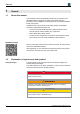
1 General 1 General 1.1 About this manual This installation manual is specifically intended for the operator of the DESIGNA parking management system and provides important information on the installation and configuration of the respective SMART MOVE components. Installation work may be carried out by skilled workers or DESIGNA trained and authorised electricians only. To ensure safe and reliable operation, please read this manual carefully and fully before installing any components.
General Hints and recommendations Functional symbols and designations 1.3 1 … highlights useful hints and recommendations as well as information for an efficient and trouble-free operation. The following symbols and designations are used in the instructions: − Instructions specified in warnings List 1.
2 Safety 2 Safety 2.1 Intended use The application SMART MOVE is part of the DESIGNA PARKING MANAGEMENT SOLUTIONS. The DESIGNA system was developed for checking entrances and exits in parking areas as well as for recording parking times and parking costs, including their automated or manual payment. The DESIGNA system is used for parking management and offers a service (a free parking space) to customers for a stipulated fee.
Scope of delivery 2.3 3 Safety standards The SMART MOVE system has been tested according to the following standards: EN 300 328 V2.1.1 Standard on the use of the radio spectrum. EN 62479:2010 Assessment of the compliance of low power electronic and electrical equipment with the basic restrictions related to human exposure to electromagnetic fields (10 MHz to 300 GHz). FCC Compliance Statement This device complies with part 15 of the FCC Rules.
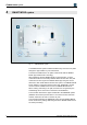
4 SMART MOVE system 4 SMART MOVE system Fig. 1: SMART MOVE system The SMART MOVE system enables ticketless entry and exit to car parks through the app installed on your smart device. The beacons installed in the car parks communicate with the SMART MOVE app via Bluetooth Low Energy. After registering with the SMART MOVE car park operator, car park customers receive the necessary SMART MOVE access data.
System requirements 5 System requirements 5.1 Technical requirements 5 The following technical requirements are necessary to ensure successful operation of the SMART MOVE system. The operator should operate the parking management system via a DESIGNA CLOUD application or using an on-premise solution with a system version X20 or higher. If no CLOUD solution is used, a DSL connection with a fixed IP address is required as well as a firewall or router. Users require a smartphone (version iOS 9.
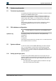
5 System requirements Fig. 2: Login group - user right Refer to the separate operator manual WinOperate – Main Menu Setting/ Set login groups. 5.3.2 Setting up app users SMART MOVE app users are listed as customers in the WinOperate system software. A season parker card is also created in WinOperate for SMART MOVE users. To be able to identify themselves with the SMART MOVE app in the system, the email address of app users must be stored in the WinOperate customer master data. 8 1.
System requirements 5 (Refer to the separate operator manual WinOperate Items and groups/ Produce card.) For the logged-in operator to be able to assign the card, the operator must have the appropriate user rights (see above). Using the Assign function, the SMART MOVE server generates a unique identification number (ETC number) for the season parker card. When setting up the app, car park customers register with their email address (see separate manual SMART MOVE parking app).
6 Technical Data 6 Technical Data Dimensions Fig. 3: Design 7 Beacon box, dimensions in mm ABS (black) Configuring beacons The beacon is housed in a plastic box and preconfigured at the factory. Prior to delivery, the latest software is installed on the beacon before it is configured and tested for the customer. This ensures the beacon is always ready for use upon delivery.
Installing beacons in the lane 8 8 Installing beacons in the lane The beacons installed in the car parks communicate with the SMART MOVE app on your smart device via Bluetooth Low Energy. These beacons are pre-configured ready for use at the factory and installed on site after delivery. To guarantee correct installation, the beacons have an ID number. Fig. 4: Example: Installed beacons at a car park entrance Two beacons are installed in each lane to facilitate vehicle recognition.
8 Installing beacons in the lane 8.1 Installation Electric voltage DANGER Danger of death due to electric shock! Contact with live components may result in death. − Installation has to be carried out by electrical technicians or DESIGNA electrical technicians or electrical technicians of DESIGNA trained and authorized dealers and partners. − Make sure that the power supply is externally disconnected and that it cannot be switched on. − Test for absence of voltage.
Installing beacons in the lane 8.1.1 8 Installing the beacon box on the entrance /exit control terminal The beacon is housed in a plastic box and installed on the side of the device facing the barrier. Power is supplied by the device. Fig. 5: Holes on the entrance /exit control terminal 1. Drill three holes in the device (see figure below): Two holes for installation on the device One hole for the cable duct Fig. 6: 2. © DESIGNA Verkehrsleittechnik GmbH DESIGNA SMART MOVE_Installation_110_ENG.
8 Installing beacons in the lane Opening the beacon box Fig. 7: Opened beacon box without any contents 1 2 Mounting plate Casing body 3. Glue the seal to the outside of the entrance /exit control terminal according to the holes 1. Seal Fig. 8: 14 Seal between device and beacon box © DESIGNA Verkehrsleittechnik GmbH DESIGNA SMART MOVE_Installation_110_ENG.
8 Installing beacons in the lane Beacon box with holes Fig.
8 Installing beacons in the lane Fig. 10: 8.1.3 Connection – beacon 6-pole micro-match connector 2. For data transfer, plug the RJ11 connector into the preconfigured port on the SBC. 3. Connect the open ends of the cable to the 5V supply of the SBC (green cable +5V, brown cable GND). Example: Installing the beacon in the DCT casing body The second beacon box is located in the DCT casing body. Power is supplied by a battery. Fig. 11: 1.
Installing beacons in the lane 8.1.4 8 Connecting the beacon in the DCT casing body Power supply The beacon in the DCT is powered by two supplied batteries (2x 1.5 V type Mono D). Fig. 12: Power supply beacon in DCT - batteries Insert the batteries into the holder on the mounting panel. Connection Fig. 13: © DESIGNA Verkehrsleittechnik GmbH DESIGNA SMART MOVE_Installation_110_ENG.
9 Configuring the IN and OUT devices 9 Configuring the IN and OUT devices The beacon (radio transmitter) on the device is connected to the SBC (Single Board Computer) via a serial interface. The parking data received from the beacon is forwarded to the DESIGNA system via the SBC. The DESIGNA system then sends the data to the SMART MOVE server. The port on the SBC must be configured accordingly in order to access the beacon. 9.
Configuring the IN and OUT devices 9.3 9 Decommissioning and disassembly 1. Disassemble the SMART MOVE components in reverse order to that described for installation (see Section 7.1. Installation) 2. Disassemble the device into its individual parts. For decommissioning and disassembly, refer to the separate operator manuals of the devices. 9.4 Disposal The SMART MOVE components consist of recyclable materials. © DESIGNA Verkehrsleittechnik GmbH DESIGNA SMART MOVE_Installation_110_ENG.
10 Version overview 10 Version overview Version 1.00 07/2020 (KS) Creation of the document. Version 1.10 09/2020 (KS) Adaptation to German version 20 © DESIGNA Verkehrsleittechnik GmbH DESIGNA SMART MOVE_Installation_110_ENG.
Version overview © DESIGNA Verkehrsleittechnik GmbH DESIGNA SMART MOVE_Installation_110_ENG.