
User's Manual


20630 / 20930 Page 9Page 8 20630 / 20930
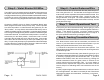
Step 6 - Coaxial Antenna Wire
Route the Antenna Wire (thick black with the clear plastic end) to the
front of the grille of the car. The last clear 8 inch length is the actual
antenna and must be exposed and not positioned behind metal. This
will allow for maximum transmitter range. Secure the clear end,
using 2 cable ties, to the grille. The more exposed the antenna, the
better the range. No antenna cable should remain coiled up - this will
greatly decrease range.
Step 7 - Quick Operational Test
At this point your alarm should be working. Before going on, test it
by pressing the middle (red) button for 1 second to get the CarFinder™
feature. If this feature is working, your alarm should be totally
functional. If you get no response from this test, go on to step 8. If
the quick operational test works, go straight to step 9.
Step 8 - Teaching Transmitters/Sensors
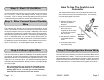
Step 5 - Violet Starter Kill Wire
The VIOLET wire is a transistor ground output that is active whenever
the system has been armed by the transmitter. This output is used
to engage a starter kill relay (optional and not included with this alarm)
to prevent the vehicle from starting whenever the alarm system is
armed. Follow the wiring diagram and instructions below if desired:
Connect the VIOLET wire to pin # 86 of a standard "Bosch" style
SPDT (Single Pole Double Throw) 30 Amp relay. Connect pin # 85
to a wire that provides +12 volts whenever the ignition key is in the
"Run" position. You may find this wire either behind the key area or
under the hood at the ignition coil/module. Locate the vehicle's starter
wire coming off of the ignition key area or under the hood before it gets
to the starter solenoid. This will be a wire that provides +12 volts only
while the key is in the "Start" position. Cut this wire in half. Connect
one side of the cut starter wire to pin # 30 of the relay. Connect the
other side of the cut starter wire to pin # 87a (the middle pin) of the
relay. Tie up the relay and wrap any exposed wires with electrical tape
to protect them from moisture and the elements. Make sure that all
wires are out of the way of moving or hot parts.
Your Smart Alarm
® comes with the transmitter pre-coded to the
receiver. If your alarm does not respond to the transmitter or you are
adding the optional wireless sensor, then do the following:
1) Pull out the 15 amp fuse for a few seconds, then replace it. The
lights will flash 4 times and the siren will chirp once confirming the unit is
in code learning mode.
2) Within 5 seconds of the first step, press button #1 (green) on your
transmitter until the lights flash once (usually hold the button for about
5 seconds), signifying that it has learned the code. If you have
additional transmitters, teach the receiver these by pressing the
second transmitter's button #1 (green) within 5 seconds of the
receiver learning the first transmitter code. (If you are adding a
wireless sensor, seperate the magnet from the switch until the
receiver chirps once indicating that it has learned the code of the
sensor.)
3) After programming the last transmitter/sensor, wait 5 seconds for
the 4 exit light flashes. Your alarm is now ready to use! Follow these
steps again to relearn new transmitters, if necessary, in the future.