
User's Manual


28636 - 28638 Page 23Page 22 28636 - 28638
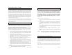
4 5 6 7 8
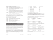
17) Norm./Dbl. Pulse Unlock DOWN UP UP UP DOWN
18) Short/Long Locks DOWN UP UP DOWN UP
19) N/A DOWN UP UP DOWN DOWN
20) Acc. Pulse/Dome Light DOWN UP DOWN UP UP
21) Trunk/Carb. Output DOWN UP DOWN UP DOWN
22) Horn-Trunk/Swap DOWN UP DOWN DOWN UP
23) Neg./Pos. Door Pin SwitchDOWN UP DOWN DOWN DOWN
24) Alarm / No Alarm DOWN DOWN UP UP UP
25-30) Not applicable
31) Reset all DOWN DOWN DOWN DOWN DOWN
Factory Anti-Theft Systems
Many vehicles come with an anti-theft system that must be temporally by-
passed for the vehicle to be remotely started.Some systems use a resistor in the
key.Others use a transponder-a small device in the key that communicates a
high security code to the vehicle before the vehicle will successfully start.
Check the following list of vehicles below.If your vehicle is listed, your ve-
hicle has an Anti-Theft System that the remote starter MUST temporally
bypass in order to start the vehicle. More information about the factory anti-
theft systems and vehicle wire colors can be found at DesignTech web page
www.designtech-intl.com. DesignTech has developed a Universal Alarm
Bypass Module,model #20402,that will temporally bypass the factory anti-
theft systems when using the remote starter.Check with your local retailer/
installer to purchase this Universal Alarm Bypass Module,model #20402 or
contact DesignTech directly.
* Press the MIDDLE button on the transmitter. The green LED on
the remote starter module or the external plug-in LED will flash
ONCE to indicate that the remote starter has changed the selected
feature from the factory setting to the option setting. Pushing the
middle button again will give you 2 flashes of the LED and will
change the setting back from the option setting to the factory set-
ting. You can go back and forth as often as needed.
* Repeat this procedure for each feature you choose to adjust from the
31 options.
* When you have adjusted all of the settings that need to be changed,
reset all the switches to the UP (or OFF) position (towards the LEDs).
This is the normal use position.
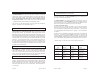
FOR OPTION SET SWITCHES
4 5 6 7 8
Normal Factory Setting/Option UP UP UP UP UP
1) Not used
2) 10 min./15 min. Run Time UP UP UP DOWN UP
3) Normal/Extended Crank UP UP UP DOWN DOWN
4) Normal/Super Crank UP UP DOWN UP UP
5) Norm/Ign. Meter Voltage UP UP DOWN UP DOWN
6) Gasoline/Diesel UP UP DOWN DOWN UP
7) Enable/No enable UP UP DOWN DOWN DOWN
8) Normal/DaytimeLights UP DOWN UP UP UP
9) Norm/Diesel Wait Start UP DOWN UP UP DOWN
10) Normal / IGN2 off dur crank UP DOWN UP DOWN UP
11) Horn Pulse/Siren Const. UP DOWN UP DOWN DOWN
12) Chirp/Silent Lock/Unlock UP DOWN DOWN UP UP
13) Active/Passive Arming UP DOWN DOWN UP DOWN
14) Normal/Lock after Ign. UP DOWN DOWN DOWN UP
15) Normal/Unlock after Ign. UP DOWN DOWN DOWN DOWN
16) Norm./Dbl. Pulse Lock DOWN UP UP UP UP