
User's Manual


28636 - 28638 Page 5Page 4 28636 - 28638
!! WARNING !!
If you are working on a newer car, you may notice bright yellow tubes or
harnesses underneath the steering column area. These are the “SRS” or AIR
BAG wires. DO NOT tamper with these wires in any way, since this could
result in personal injury and/or damage to the air bag system.
Battery gases are explosive. Do not smoke while working near the car’s
battery.
!! CAUTION !!
When fishing wires through the car’s firewall, be sure to protect them from
sharp metal edges and from hot surfaces on the engine.
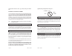
NOTE: Some installers hook a battery charger up to the vehicle’s battery
during the installation. This is fine, but it must be removed before running
the vehicle under remote car starter control.
INSTALLATION INSTRUCTIONS
1 BEFORE YOU START
Take this time to read through the entire installation manual. Reading
the manual now will save significant time in the long run. ALL STEPS
ARE CRITICAL.
The installation information section or our web site www.designtech-
intl.com is available 24 hours/day to provide you with up to date vehicle
wiring information for your particular vehicle if needed.
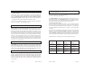
Wire Harnesses: Always check your wire harness before installing to
make sure that it matches the list/drawing on page 4 of the manual. You
can use the BLUE WIRE COLOR SHEET to help determine the col-
ors of the wires in your vehicle -- but be sure to always check these using
a volt-meter since vehicle wire colors can change from year to year in
vehicles.
When you have read the entire manual, and paid close attention to every
step, start the installation by putting the Yellow WARNING STICKER
under the hood. Pick a surface that is readily visible with the hood open
and will not be easily covered with grime. Make sure that the surface is
clean and grime free before applying the sticker.
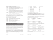
Color Function Type Required
Thick Pink Power(+12V) Yes
Thick White Accessory Relay output Yes
Thick Yellow Starter Relay output Yes
Thick Blue Ignition 1 Relay output Yes
Thick Green Ignition 2 Relay output Maybe - Consult Wiring Guide
Black Ground Yes
Color Function Type Required
Red/Black Diesel “wait to start” Input (+/-) No
Red/White Remote Input Input (-) No
Green Tach Input No
Violet Hood Input (-) Yes
Orange Brake Input (+) Yes
Color Function Type Required
Yellow Lights Relay output No
Blue Horn Relay output No
Brown Acc. Pulse/Dome Light Output (-) No
Brown/White Alarm Disable Output (-) Maybe
White/Black Ignition 3 Output (-) No
Color Function Type Required
Gray Alarm Trigger Input (-) No
White Ground out while armed Output (-) No
Green/White Trunk / Carburetor Output (-) No
Gray/Black Door Pin Switch Input (-) No
Color Function Type Required
White/Red Lock Common Relay output No
Yellow/Green Unlock Normally Closed Relay output No
White/Green Lock Normally Closed Relay output No
Yellow/Red Unlock Common Relay output No
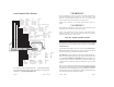
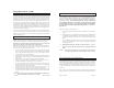
Plug In Switch
Plug In LED
AutoCommand Wire Harness
Optional Shock Sensor Jack
For vehicle specific wiring information -- consult the Blue Sheet
for general information and consult our Web sit for more specific
information. www.designtech-intl.com.