
User's Manual


28636 - 28638 Page 7Page 6 28636 - 28638
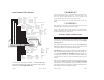
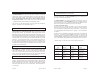
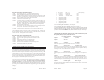
Ignition Key Diagram for Steps 4-7
Lock/Off ACC
RUN
ACC START
4 Thick Blue Wire Ignition 1
Attach the Thick BLUE 14 gauge wire (Ignition 1) to the ignition 1 wire
coming off the key switch behind the steering column. This is a wire which
shows positive (+12v) on the test meter in the run and start position, but is off
in the lock/off and accessory position.
5 Thick Green Wire Ignition 2
Most cars (especially newer cars) have a second ignition wire that is neces-
sary. Use the Thick GREEN 14 gauge (Ignition 2) wire for this connection.
This is a wire that shows positive (+12V) on the test meter in the run position.
It may be best to leave this wire until the end to determine whether the vehicle
needs this wire to operate some of the accessories. Note -- setting dip-switch
option 10 (described in Step 29) will cause this wire to be off during crank.
6 Thick White Wire Accessory
Attach the Thick WHITE 14 gauge wire to the accessory wire coming off of
the key switch behind the steering column area. This is a wire which shows
positive (+12v) on the test meter in the run and accessory position, but is off
in the start and off position.
All dipswitches should be OFF (up position) during the installa-
tion.
POWER & IGNITION WIRES
The AutoCommand® module (large black box) will be installed under the dash,
once all wiring has been completed. Do not mount the module at this time
because you will need to check the diagnostic lights as the installation
progresses. Locate (or drill a hole) in the firewall to run all of the long wires (12
AWG PINK, 18 AWG YELLOW, VIOLET, GREEN, and BLUE) through the firewall
to the engine compartment. The remaining short wires stay in the passenger
area. Leave about a foot of length at the harness end under the dash for ease of
working and visual access to the diagnostic lights.
(Note: Always connect up the
Black and Pink wires before connecting up
any of the other wires.)
2 Black Wire Ground
Optimum ground connection is critical for proper operation of this unit, as well
as transmitter range. Connect this BLACK wire to a very good clean chassis
ground in the driver’s side kick panel area. Use the small red ring terminal if
needed. The metal bracing around or beneath the dash board is not adequate.
3 Long Pink & Short Pink Wire Power (+12V)
The LONG PINK wire goes through the fire wall and connects to the SHORTER
PINK wire with fuse holder. We recommend getting power directly at the
battery +12V terminal. Connect the ring terminal on the SHORT PINK wire to
the +12 volt terminal of the battery. Strip back some insulation and then solder
the two ends of the PINK wires together, or use the Yellow Butt connector to
connect these. Either way, you must have a very good connection.
Install the
30 Amp green fuse.
As soon as the Pink (Power) wire is connected the GREEN LED will come on and
go out. (If the unit is already initialized, the GREEN LED will come on for several
seconds while the RED LED flashes 4 times.)
NOTE: WE STRONGLY RECOMMEND GETTING POWER AT THE
BATTERY. ALSO, FAILURE TO INSTALL THE FUSE HOLDER AND
30 AMP FUSE TO THE PINK WIRE VOIDS ALL PRODUCT WAR-
RANTIES, BOTH WRITTEN AND IMPLIED!