
User's Manual


28636 - 28638 Page 9Page 8 28636 - 28638
11 Orange Wire Brake Shut-off Control Harness
The ORANGE 18 gauge wire will disable the remote starter when the brake
pedal is pressed down. This is an added anti-theft safety feature. This con-
nection is usually made under or behind the brake pedal linkage at the switch.
Connect the ORANGE wire to the wire that receives +12V only when the
brake pedal is pressed down. Any +12V input on this wire will shut off the
AutoCommand®. In some cars, the ignition must be on to see power at the
brake wire. This wire must be hooked up. This is a critical safety feature.
This connection is also required for several options discussed later.
NOTE: With the Valet switch connected and in the ON position, pushing on
the brake pedal with the hood open (hood pin switch at ground) at this time
will cause the ignition wires to power up unless the unit has been initialized
as described in the next step.
12 Initializing the Remote Starter
BEFORE THE CAR WILL START FOR THE FIRST TIME, YOU MUST
INITIALIZE THE REMOTE STARTER WITH THE HOOD OPEN.
A. The Remote Starter requires the installer to open the hood, and press and
hold the brake pedal. If the unit is not initialized at this time -- this
action will cause the ignition outputs to come on (i.e. the dash lights come
on) informing you that the unit is
not initialized.
B. While depressing the brake (with the engine off and the hood open), turn the
key to the “RUN” (not “start”) position.
C. Put the car in GEAR from the PARK position.
D Put the car back in PARK and release the brake. The GREEN LED should
have flashed twice when you did this -- then 2 seconds later, the Green LED
will stay on while the Red LED will give 4 quick flashes. (The remote starter
looks at the vehicle’s neutral safety switch and checks for an automatic trans-
mission during this step.)
E. Turn off the key and remove key from ignition.
You can confirm that the unit has been ‘initialized’ — simply turn the ON/OFF
switch OFF and then ON. The GREEN LED (or dashmount LED) on the Auto-
Command module will flash once immediately as the switch is flipped from the off
7 Thick Yellow Wire Starter
Attach the YELLOW 14 gauge wire to the starter wire coming off of the key
switch in the steering column area. This wire is hot (+12V with a meter) in the
start position only. It is off in all other positions.
CONTROL HARNESS
8 On/Off Plug-in Control Switch
This switch must be installed for the remote starter to operate. Mount the
switch then plug this switch harness into the AutoCommand module at the 2
pin white connector. (See diagram on page 4).
Mount the control switch so that the “On” position is facing upward.
Connection of this switch is mandatory.
9 Red/Black Wire Diesel “wait to start” / PAGER Control Harn.
This wire is used in diesel vehicle applications - and is optional. This wire
can be hooked up to the “wait to start” light’s switched wire behind the dash,
or directly to the glow plug wire. The sense wire must change state when the
Wait to Start light turns on. If dip switch option 9 (described in Step 29) is
set, this wire will feed information to the remote starter as to when to begin
starting the vehicle.
This wire can also be used with DesignTech’s Nationwide Pager (model
28010). In Data-Link mode, one can control all features of the remote starter
via any telephone. If the pager is used in Data-Link mode, this wire cannot be
used for Diesel applications. Follow the separate Pager directions for instal-
lation.
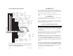
10 Violet Wire Hood Pin Switch Control Harness
The hood pin switch must be installed for the unit to initialize and work
properly. It prevents operation of the remote starter when the hood is open.
Attach the VIOLET 18 gauge wire to the supplied pin switch using the hard-
ware provided. Be sure to have a good ground connection.
If you already have a hood pin switch which is being used by a car alarm
system, you may share the wiring -- but be sure to diode isolate each wire
going to the hood pin switch. See following diagram: