LCC/LCD2-14-3 NON PASS-THROUGH SERIES WITH PROTOCOL PLUS ™ INSTRUCTION MANUAL C-198 PN 161871 REVISION M 3/2010
NOTICE Users of this equipment must comply with operating procedures and training of operation personnel as required by the Occupational Safety and Health Act (OSHA) of 1970, Section 6 and relevant safety standards, as well as other safety rules and regulations of state and local governments. Refer to the relevant safety standards in OSHA and National Fire Protection Association (NFPA), section 86 of 1990.
PREFACE This manual is your guide to the Despatch LCC/LCD2-14-3 SERIES ovens. It is organized to give you the information you need quickly and easily. The INTRODUCTION section provides an overview of the oven. NOTE: Read the entire INTRODUCTION and THEORY OF OPERATION before installing the oven. The OVEN OPERATION section details the function and operation of assemblies and subassemblies on the oven. The INSTRUCTIONS section provides directions on unpacking, installing, operating and maintaining the oven.
Revision A (7-02): Initial Creation. Revision B (11-02): Drawing Changes, add line connection detail. Revision C (08-03): Update drawings. Revision D (11-03): Updated to Protocol Plus Version 4.0. Revision E (03-04): Update drawings, change Class A warning. Revision F (06-04): Change water drain/outlet temp rating. Revision G (08-06): Update to current design.
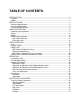
TABLE OF CONTENTS INTRODUCTION ............................................................................................................. 1 Features ...................................................................................................................... 2 Options ........................................................................................................................ 2 SPECIFICATIONS .............................................................................................
Key Functions ........................................................................................................ 33 Outputs .................................................................................................................. 34 Relay (Continued) .................................................................................................. 35 Communication ...................................................................................................... 35 Optional Software.......
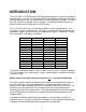
INTRODUCTION The LCC/LCD2-14-3 SERIES offers HEPA filtration for processes where minimization of contamination is essential. The removable HEPA (High Efficiency Particulate Air) filter is designed to provide a constant flow of clean air to the product being heated. The HEPA filter with silicone seal provides 99.99% filtration. A magnehelic differential pressure gauge monitors pressure drop across the HEPA filter.
Features Despatch Protocol Plus microprocessor-based digital programmable control, with simultaneous digital readout of both setpoint and actual temperatures. CE and SEMI S2 compliance, including yellow and red disconnect switch/EMO mounted in the front control panel door. Manual reset high-limit control. Proportioning temperature control using solid state relays. Four (4) inches of insulation minimizes heat loss, external thermal spots and air leakage.
SPECIFICATIONS Electrical Specifications If your line voltage is much lower than the oven voltage rating, heat up time is significantly longer and motors may overload or run hot. If your line voltage is higher than the nameplate rating, the motors may run hot and draw excessive amps. If the line voltage varies more than 10% from the oven voltage rating, some electrical components such as relays, temperature controls, etc. may operate erratically. Power connection is performed by the user.
Physical Specifications CHAMBER SIZE INCHES (CM) MODEL WIDTH** DEPTH HEIGHT CAPACITY IN CU. FT. (LITERS) OVERALL SIZE INCHES (CM) APPROX. WEIGHT HEIGHT SHELVES PROVIDED ON SHELF CENTERS WIDTH DEPTH MAX. # OF SHELVES LBS. (KG) NET LBS. (KG) SHIPPING LCC/LCD2-14 25.5 (64) 26 (66) 37 (94) 14 (396) 47.5 (121) 41.5 (105) 71 (180) 2 ON 3” 955 (434) 1050 (477) 11 25.5 (64) 26 (66) 37 (94) 14 (396) 47.5 (121) 41.5 (105) 71 (180) 2 ON 3” 955 (434) 1050 (477) 11 25.
OVEN INSTRUCTIONS The OVEN INSTRUCTIONS section provides directions on unpacking, installation, operation and maintenance of the Despatch LCC/LCD2-14 Series Ovens. Unpacking and Inspection Remove all packing materials and thoroughly inspect the oven for damage of any kind that could have occurred during shipment. See whether the carton and plastic cover sheet inside carton are still in good condition. Look at all outside surfaces and corners of the oven for scratches and dents.
Set-up 1. Select the location for installing your oven. 2. Make sure the oven is level and plumb; this will assure proper heat distribution and operation of all mechanical components. The rear of the oven may be placed against a wall. If possible, provide room at the sides and rear of the oven for maintenance. WARNING: Do not use the oven in wet, corrosive or explosive atmospheres unless this oven is specifically designed for a special atmosphere.
CAUTION: Design the drain system to prevent operator injury from high temperature or pressure buildup. Piping must be able to withstand short periods of up to 650 °F (343 °C) temperatures. Drain lines should be insulated and/or warning labels installed that a hazard exists. WARNING: Never allow drain to be plugged as a hot oven will generate a small amount of steam when the water is first turned on. STEAM BURNS! LCC/LCD2-14-3 POWER & EXHAUST CONNECTIONS Conduit fitting for customer power line.
LCC/LCD2-14 UTILITY CONNECTIONS FOR NITROGEN AND WATER COOLING Nitrogen or Clean Dry Air Inlet. 70 to 80 PSI (4.83 to 5.52 Bar). Used for Nitrogen/Clean Dry Air Purge and Maintain Inlet and to purge water out of the coil prior to heating the oven. 3/8” NPT female brass connections are provided. During cooling cycle, water flows through the water coil and out this connection. 3/8” NPT female brass connections are provided.
Wiring NOTE: The oven must be directly WARNING: hardwired to the disconnect switch All grounding and safety equipment must be on the equipment panel. A one (1) in compliance with applicable codes, inch conduit run is provided from the ordinances and accepted safe practices. rear of the lower oven compartment, which is marked LINE CONNECTIONS to the front equipment panel, through which the line voltage power wiring can be connected to the disconnect switch labeled LINE CONNECTIONS in the front of panel.
HEPA Filter Installation Technicians responsible for installing the filter should use caution. The filter is delicate and must not be damaged during installation. Any filter unit dropped, whether or not in the carton, should be examined for damage. Equally important, the filter unit must be installed so that unfiltered air will not leak past the unit. WARNING: Make certain that power is disconnected from the oven before removing or replacing the HEPA filter. 1. Remove the filter from the carton. a.
Check that the gaskets are cemented firmly to the filter frame and that the gasket pieces are butted or mated at the joints. 3. Pull the shelf out from the oven and set it aside. NOTE: If it is necessary to move the equipment after the burn-off process, considerable care should be used. The binder which gives strength to new filters is now burned-off and WARNING: Make certain that power is disconnected from the media is very fragile.
The following procedure is recommended: 1. Locate the equipment exhaust opening where chamber air is being expelled. If the oven filter is burned off in a clean area, be sure to handle the equipment exhaust appropriately. If the equipment is large and the exhaust stack is a permanent service connection, it should be connected before the burn-off process is run.
Filter High Limit The LCC/D2-14*-3 series ovens have been equipped with a redundant high limit device to protect the HEPA filter. The sensor for the high limit is located before the air inlet of the HEPA filter. The high limit device is located in the lower compartment of the oven. If the oven temperature exceeds the factory set Filter High Limit temperature, the high limit will trip, shutting down the heater and protecting the HEPA filter.
OVEN OPERATION Oven The LCC/LCD2-14 Series oven is a class 100 clean room oven with HEPA (High Efficiency Particulate Air) filtration. This oven is ideal for processes where minimization of contamination is essential. Forced convected airflow provides rapid uniform distribution of heat. A HEPA (High Efficiency Particulate Air) filter is mounted in a stainless steel frame in the supply plenum. These filters are 99.97% effective in filtering 0.3 micron particles.
System Control A Despatch Protocol Plus controller/high-limit device is used to control the unit. This is located on the control panel of the oven. See the section on the Protocol Plus controller for detailed operation. The Protocol Plus controller provides temperature control for the process. The Protocol Plus controller provides outputs for the cooling/exhaust fan, End of Cycle/door lock, and purge and maintain operation for inert atmosphere.
Protocol Plus Controller on upper portion of control panel Lower Portion of Control Panel Main Disconnect Switch: This disconnect switch is connected to the load break switch behind the panel that disconnects or connects power from the main line. Power Stop/Stop Push-button: Pushing start energizes the motor and control circuit, providing the main disconnect switch is on and door is closed. Pushing stop will shut down the oven.
HEPA Filters HEPA (High Efficiency Particulate Air) filters are used to limit particulate size in the work chamber to 0.3 microns or less. NOTE: Chamber temperature transitions must not exceed 1.25°C/minute in order to maintain class 100 chamber conditions. An optional (Termikfil brand) filter is available for transition rates up to 5°C/minute. Consult factory. Definitions HEPA - High Efficiency Particulate Air Burn-Off - A process for getting rid of the binder contained in the filter. D.O.P.
Handling The filter is shipped in the original carton or package that the filter manufacturer uses. This will give good storage and maximum protection from dirt and moisture. HEPA filters should be stored and moved in the shipping carton with in the upright position. Handling should be kept to a minimum. During installation the filter should be removed from the shipping carton and installed directly into the oven.
Validation Testing Based on the issues discussed in this section, Despatch recommends the following test sequence for pharmaceutical Class 100 ovens. 1. Proper installation of the HEPA filters. 2. Ambient air challenge to determine integrity of oven chamber and filter gaskets. 3. Proper filter burn-off procedure. 4. Class 100 testing inside the work chamber. The Necessity of the Burn-off Process HEPA filters contain a binder material, which protects the filter media during production and shipping.
HEPA Filter / Magnehelic Pressure Gauge The LCC Series oven is equipped with a Magnehelic pressure gauge which measures the pressure in front of the HEPA filter. As the filter becomes dirty, the pressure will increase. Despatch recommends changing the filter when the pressure is 1” w.c. greater than when the filter was first installed.
OPERATING Users and operators of this oven must comply with operating procedures and training of operating personnel as required by the Occupational Safety and Health Act (OSHA) of 1970, Section 5 and relevant safety standards, and other safety rules and regulations of state and local governments. Refer to the relevant OSHA and National Fire Protection Association (NFPA) safety standards.
Pre-Startup Checklist Know the system. Read this manual carefully. Make use of its instructions and explanations. The know how of safe, continuous, satisfactory, trouble-free operation depends primarily on the degree of your understanding of the system and of your willingness to keep all parts in proper operating condition. WARNING: Do not use any flammable solvent or other flammable material in this oven.
Operating Procedure Starting the Oven 1. Turn the yellow/red DISCONNECT SWITCH to ON. 2. Press the POWER pushbutton ON switch. The door remains unlocked. NOTE: during the process cycle the door is locked. To unlock the door press the STOP push-button or remove power from the oven by using the disconnect switch (optional “Class A” equipped units) Once the power switch is turned on, the recirculation fan and exhaust fan are turned on, the airflow switch will actuate and the purge timer will begin timing.
5. Run the desired profile from the Protocol Plus controller. Press the Select key until Profile is displayed (you can press the Run key at any time to activate Profile Mode). Press the key to display the desired profile to run. To start Profile Mode, press the Run key. NOTE: The display will change from Stop to Run and the segment time remaining, along with the current segment number, will be displayed. 6. The oven profile cycle is in process and the door is LOCKED.
6. The first segment of the program is the PURGE MODE. Set the nitrogen flow meter to 300 - 350 SCFH. This program energizes the purge solenoid valve. 7. The second segment is the MAINTAIN MODE, the purge solenoid valve is de-energized and the maintain solenoid is energized to maintain the nitrogen level to less than the purge level. Adjustment is made with a needle valve located in the front bottom of the oven.
4. If the high limit trips repeatedly, identify the cause and correct the problem. Class A Configuration The “Class A” configuration is used for handling flammable solvents. NOTE: With this option the exhaust fan is wired to be ON at all times. The “Class A” option has an explosion relief panel and purge interlock devices: In case the LEL (lower explosive limit) is exceeded, and an explosive mixture is ignited in the oven, the explosion relief will rupture, preventing any more physical damage to the oven.
Class A Operation Verify the purge time with the time listed on the nameplate. Close the main disconnect switch. Press the START push button. Start the profile; at this time the exhaust fan will start, the airflow switch will actuate, and the purge timer will begin timing. CLASS A OVENS ONLY! WARNING: “Class A” ovens are designed for a specific amount of solvent. Exceeding this amount could result in an explosion.
Maintenance Do not attempt any service on this oven before opening the main power disconnect switch. Checklist WARNING: Disconnect the main power switch or power cord before attempting any repair or adjustment. Do not allow flammable solvents, combustibles, or other organic material to accumulate in Class A ovens, as this could lead to fire or explosion, particularly if the maximum solvent rating of the oven is exceeded. Keep equipment clean. Gradual dirt accumulation retards airflow.
PROTOCOL PLUS CONTROL The special features of the Protocol PlusTM control include: PID tuning Ramp/Soak programming of up to 64 segments Segment looping and profile linking Built-in manual reset high limit control Built-in process timer Dedicated LED display for process temperature Multi-purpose two-line LCD display with backlight Auto-tuning Security access Process temperature retransmission signal Digital inputs for remote profile control Real time clock Optional relay outputs for events, alarms, or end-o
Protocol Plus Faceplate and Wiring Diagram 30
Operating Modes The Protocol Plus control has five modes of operation available: Stopped Mode: All control and relay outputs are off. Stopped Mode is integrated into each of the following four modes of operation. Manual Mode: Control operates as a single setpoint control until Stopped mode is accessed Timer Mode: Control operates as a single setpoint control until preset time period has expired. Profile Mode: Control operates as a ramp/soak profiling control until the end of the profile.
High Limit The control has an integrated high limit function which will disable the heater output when tripped. If the high limit does trip, the relay will need to be manually reset. When the high limit relay is tripped, the Hi-Limit indicator will be lit. Allow the oven to cool several degrees (or increase the high limit setpoint) and then press the Reset key. The indicator will turn off.
Displays The Protocol Plus control has two displays. A dedicated LED upper display shows the oven temperature. A two-line LCD lower display provides information on control status, high limit temperature, and allows changes to be made to the control settings. Key Functions The Protocol Plus control has seven keys that provide operation. Select key: Press to select mode of operation. In Setup Mode, to select profile number or relay.
Outputs The Protocol Plus control has seven different outputs available. Heating output: The control output is a DC voltage open-collector output which is time-proportioned and designed to control a heat control device such as a solid state relay. High limit: The high limit output is a form C relay which is energized under normal operating conditions.
Relay (Continued) Use the Relay Card Optional Ay p/n 144562 to add relays to the standard controller. Each relay card contains two relays (maximum of two cards Ay’s allowed). Communication The Protocol Plus control has optional MODBUS communication available which can communicate via RS232, RS422, or RS485 to a computer. See communications option assembly p/n 161957 for board and cable assembly. Please refer to the MODBUS communications manual which comes with this option.
INSTRUCTIONS Start-Up These instructions are provided as a quick reference for operating the Protocol Plus control. If the Profile Mode is to be used, or the configuration of the control needs to be changed, please refer to the Setup Mode instructions before operating the control. For more detailed operating instructions refer to the Operation instructions for the mode you wish to use. Upon initial power-up the control is in Manual/Stopped Mode (unless the Autostart or Fast Start Modes are active).
Operation Manual Mode Press the Select key until Manual is displayed (note you can press the Run key at any time to activate Manual Mode). 1. Press the Menu key to display the Process Temperature Setpoint (setpt). You can change the Setpoint with the keys. Note: If the SPChange parameter on the Enable page in Setup Mode has been set to DISABLED, it must be changed to ENABLED before any changes to the process temperature and high limit setpoints can be made. 2.
Timer Mode 1. Press the Select key until Timer is displayed (note you can press the Run key at any time to activate Timer Mode). 2. Press the Menu key to display the Process Temperature Setpoint (Setpt). You can change the Setpoint with the keys. Note that if the SPChange parameter on the Enable page in Setup Mode has been set to DISABLED, it must be changed to ENABLED before any changes to the process temperature and high limit setpoints can be made. 3.
Profile Mode 1. Press the Select key until Profile is displayed. “None” may be displayed if a profile has not been selected or no profiles entered. 2. Press the key to display the desired profile to run. 3. To start Profile Mode, press the Run key. The display will change from Stop to Run and the segment time remaining, Temperature Setpoint, Profile #, along with the current segment number, will be displayed. To return to Stopped Mode, press the Stop key.
Note that once you activate Auto Start, you can continue to use all operating modes as normal. If an operating mode is running at the time of a preset Auto Start function, and Auto Start is activated, the existing operating mode will override the auto Start function and the Auto Start will not turn on. Note: All process Set to Run in Auto Start Mode must be at least one minute long for all Run Modes (Manual, Timer, and Profile).
Instructions for Setup Mode Pages Program Page Programming of the profiles is provided on the Program Page. Eight profiles are available with up to eight ramp and soak segments per profile. If the optional relay outputs are installed, they must be configured as alarms or events on the Relay Outputs Page before they can be utilized. If configured as event outputs, these relays can be used as time or temperature events.
Menu Item Display Description Ramp Time Seg 1 Pro-1 Seg-1 Ramp Time Ramp time for segment 1 of profile Event 1 Set Value* Pro-1 Seg-1 Ramp Event 1 Event 1 setting for segment 1 ramp of profile Event 2 Set Value* Pro-1 Seg-1 Ramp Event 2 Event 2 setting for segment 1 ramp of profile Event 3 Set Value* Pro-1 Seg-1 Ramp Event 3 Event 3 setting for segment 1 ramp of profile Event 4 Set Value* Pro-1 Seg-1 Ramp Event 4 Event 4 setting for segment 1 ramp of profile Soak Temp Seg 1 Pro-1 Seg 1 So
There are eight profiles available. Profile # Segment# Recipe segments 1 through 8 may be programmed, each with its own set of events, ramp and soak times, and soak temperature. Ramp Time The time required to ramp from one setpoint up to another setpoint. Values between 0 and 99:59 are allowable. In the Protocol Plus controller, the profile ramp and soak times are stored without units. Units are set as either hours and minutes (HH:MM) or minutes and seconds (MM:SS).
Sample Profile Programming Table Profile Number____1______ Segment Time 1 Profile Name__________ Ramp Events 2 3 Soak Temperature 4 Time 1 01h00 100 01h00 2 02h00 50 00h01 3 00h00 4 5 6 7 8 High Limit Setpoint 115 Loop From Seg No Loop To Seg No Loop Number 0 Link To Pro No Guar Soak Band 10 44 Events 1 2 3 4
Auto Start Page The Auto Start Page can be configured to automatically start Manual, Timer or Profile Mode at a specified time and day. Note that if Auto Start Enable is set to Yes in the Setup Mode, the Auto Start feature is not turned on - it is available to the operator to be activated in Stopped Mode. To configure the Auto Start feature: 1. Access the Setup Mode. 2. Press the Page key until Auto Start is displayed. 3. Press the Menu key.
Menu Item Enable Autostart Sunday mode Sunday time Monday mode Monday time Tuesday mode Tuesday time Wednesday mode Wednesday time Thursday mode Thursday time Friday mode Friday time Saturday mode Saturday time Display Description Range Auto Start Enable Enable (yes) or disable (no) the Autostart function No, Yes Set mode on Sunday to activate Off, Manual, Timer, Pro-1 to Pro-8 Set time on Sunday for mode to activate 00:00 to 23:59 Set mode on Monday to activate Off, Manual, Timer, Pro-1 to Pro-
PID Page The PID Page contains parameters which control the response to the setpoint and process variable input. To access the PID Page, enter the Setup Mode. Press the Page key until PID is displayed. Press the Menu key. Each parameter can be changed by pressing the Menu key until the desired parameter is displayed, and then pressing the keys to change the value.
1. Access the Setup Mode. 2. Press the Page key until the display reads AutoTune. Press the the AutoTune. key to enable 3. Press the Page key for three seconds to exit Setup Mode. 4. Cycle power to the instrument. 5. Set Manual Mode to run. The display will alternately display AutoTune and Manual. If the Manual Mode setpoint is less than 50 degrees higher than the actual process temperature, the AutoTune function will create an error condition.
Control Page The Control Page contains various parameters which control miscellaneous functions. To access the Control Page, enter the Setup Mode. Press the Page key until Control is displayed. Press the Menu key. Each parameter can be changed by pressing the Menu key until the desired parameter is displayed, and then pressing the keys to change the value.
Communication Page (optional) The Communication Page contains parameters for the communications feature. To access the Communications Page, enter the Setup Mode (see description earlier in this manual). Press the Page key until Communication is displayed. Press the Menu key. (NOTE: If there is no change in the display, the controller does not have the communications board installed.
Relay Outputs Page (optional) The Relay Outputs Page configures the four alarm/event outputs. Each output has a dedicated indicator light and can be configured as a temperature alarm, profile event, or end of cycle output. Temperature alarms can be of type process high, process low, deviation high, deviation low, or deviation band. To access the Relay Page, enter the Setup Mode (see description earlier in this manual). Press the Page key until Relay is displayed.
Test Page The Test Page contains parameters which allow manual control of the heat control and optional relay outputs and should be used only for testing the functionality of the control instrument. Do not operate the oven for processes using the Test Page. To access the Test Page, enter the Setup Mode (see description earlier in this manual). Press the Page key until Test is displayed. Press the Menu key.
Zone Calibration Page The Zone Calibration Page allows adjustment of the displayed temperature versus the actual temperature measured by the control thermocouple. This may be desirable in certain conditions where the center of the oven chamber is not the same temperature as the control thermocouple. This may occur when the oven is not allowed to soak at a constant temperature for long periods of time, or the oven is being used at high temperature.
As an example, the control is displaying 400°F with the setpoint being 400°F, but the center of the oven chamber is actually 395°F. This can occur due to oven wall losses and product loading variations. The operator may change the zone calibration so that the center of the oven is 400°F when the display reads 400°F. In this case operate the oven in manual mode with a setpoint of 400°F. Record the center of the chamber (as measured with an independent sensor).
Sensor Calibration Page The Sensor Calibration Page has parameters which can change the internal calibration of the temperature sensor input signal. There is a low and high calibration point for both the control sensor and the high limit sensor. To calibrate the instrument, allow the control to warm up for at least 30 minutes. To access the Sensor Calibration Page, enter the Setup Mode (see description earlier in this manual). Press the Page key until Control Sensor is displayed. Press the Menu key.
18. Connect a calibration instrument with a type J thermocouple output to the control sensor input. 19. Connect a voltage measurement device to the retransmit output terminals. 20. Set the calibration instrument output to the temperature value of the RetOutLo parameter from the Control Page. 21. Adjust the RetCalLo * value using the keys until the voltage measurement device reads 1VDC. 22. Press the Menu key. 23.
Enable Page The Enable Page controls access to the other Setup Pages. The setpoint minimum and maximum values, and the security passwords are also set on the Enable Page. To access the Enable Page, enter the Setup Mode using a level 2 access code (see description earlier in this manual). Press the Page key until Enable is displayed. Press the Menu key. Each parameter can be changed by pressing the Menu key until the desired parameter is displayed, and then pressing the keys to change the value.
Digital Inputs (optional) The Protocol Plus control can be run by external inputs wired to the control from an external source such as a PLC or control panel switches. The external run operation can Run, Hold or Stop profiles 1 through 7 (profile 8 can not be operated externally). Refer to the table below for the inputs required for the desired operation. NOTE: A profile must be created in the program page before trying to run a profile number.
Error Messages and Alarms The Alarm Status Hi-limit LED is flashing. This indicates a problem with the thermocouple, or the Hi-limit setpoint has been exceeded. Once the problem has corrected, press the Reset pushbutton. The Alarm Status Soak LED is flashing. This indicates that the oven temperature has not entered or dropped out of the soak band and the soak timer has stopped. The top LED Display reads OPEN and the lower LCD display reads CONTROL SENS ERR.
Quick Reference and Default Values Program Page Menu Item Ramp Time Seg 1 Display Pro-1 Seg-1 Ramp Time Default 00:00 Event 1 Set Value Pro-1 Seg-1 Ramp Event 1 Off Range 00m00s to 99h59s Off, On Event 2 Set Value Pro-1 Seg-1 Ramp Event 2 Off Off, On Event 3 Set Value Pro-1 Seg-1 Ramp Event 3 Off Off, On Event 4 Set Value Pro-1 Seg-1 Ramp Event 4 Off Off, On Soak Temp Seg 1 Pro-1 Seg 1 Soak Temp 68°F Soak Time Seg 1 Pro-1 Seg 1 Soak Time 00:00 Event 1 Set Value Pro-1 Seg-1 Soak Eve
Programming Table Profile Number__________ Profile Name__________ Segment Time 1 Ramp Events 2 3 Soak 4 Temperature 1 2 3 4 5 6 7 8 High Limit Setpoint Loop From Seg Loop To Seg Loop Number Link To Pro Guar Soak Band 61 Time Events 1 2 3 4
Autostart Menu Item Display Default Range Enable Autostart Auto Start Enable No No, Yes Sunday mode Auto Start Sun Mode Off Off, Manual, Timer, Pro-1 to Pro-8 Sunday time Auto Start Sun Time 00:00 00:00 to 23:59 Monday mode Auto Start Mon Mode Off Off, Manual, Timer, Pro-1 to Pro-8 Monday time Auto Start Mon Time 00:00 00:00 to 23:59 Tuesday mode Auto Start Tue Mode Off Off, Manual, Timer, Pro-1 to Pro-8 Tuesday time Auto Start Tue Time 00:00 00:00 to 23:59 Wednesday mode Aut
Control Menu Item Display Default Range Cycle Time Control Cycle Time 1 1 to 60 seconds Setting High limit setpoint Control Hi-Lim SP Max HiLimSP MinHiLimSP - MaxHiLimSP* High limit band Control Hi-Lim Band Off Off, 3°C to 11°C (5°F to 20°F) Power fail recovery Control PwrFRec Stop Stop, Restart, Hold, Resume Recovery time limit Control PwrFTime 00m00s 00m00s to 99m59s Powerup start enable Control EPwrStrt Dis Dis, En Powerup Start Mode Control StrtMode Off Off, Manual, Timer
Real Time Clock Menu Item Display Default Range Setting Day of the week Clock Day Mon Time of day Clock HH:MM 00:00 Sun, Mon, Tue, Wed, Thu, Fri, Sat 00:00 to 23:59 Reset clock Clock UP to Reset CLK* Ready Ready, Done * if the key is not pressed, the clock values will retain their original values, the display will change to Done if the clock is reset Relay Outputs (optional) Push Select key to select relay.
Test Menu Item Display Default Range Heater output Test HeatOut Off On High limit relay Test HiLimOut Off On Relay 1 output Test Rly1 Out Off On Relay 2 output Test Rly2 Out Off On Relay 3 output Test Rly3 Out Off On Relay 4 output Test Rly4 Out Off On High Limit Sensor Test HL Temp (sensor reading) Setting Zone Cal Menu Item Display Default Range Zone 1 actual Zone Cal Zone1Act 38°C Zone1 displayed Zone Cal Zone1Dis 38°C Zone 2 actual Zone Cal Zone2Act 260°C Zon
Enable Page Menu Item Display Default Range Profiles Enable Profile 1-8 Yes Yes or No Autostart Enable Auto Start No Yes or No ** PID Enable PID Yes Yes or No Control Enable Control No Yes or No Communication Enable Communication No Yes or No ** Real Time Clock Enable Clock No Yes or No ** Relay outputs Enable Relay 1-4 No Yes or No ** Test Enable Test No Yes or No Zone Calibration Enable Zone Cal No Yes or No Sensor Calibration Enable Sensor Cal No Yes or No Setp
Technical Specifications UL, cUL listed: UL file E136675 CE compliance to: EMC Directive 89-366/EEC European Standard EN55011/1991 European Standard EN50082-2/1995 Power supply: 100 to 240 VAC +10% -15%, 50-60Hz, 30VA Maximum 12 to 24 VAC/VDC +/-10%, DC to 60Hz, 30VA Maximum Temperature: Humidity: Storage -20 to 60°C Operating 0 to 50°C 90% or less, non-condensing Sensor inputs: Type J thermocouple -73°C to 760°C (-100°F to 1400°F) Input impedance 1M ohm or greater Common mode noise rejection of 14
APPENDIX: DRAWINGS The following pages contain electrical drawings for the LCC/LCD2-14*-3.
69
70
71
72