LFD SERIES OVEN WITH PROTOCOL PLUS ™ INSTRUCTION MANUAL C-186 PN 143378 REVISION H 3/2009
Notice Users of this equipment must comply with operating procedures and training of operation personnel as required by the Occupational Safety and Health Act (OSHA) of 1970, Section 6 and relevant safety standards, as well as other safety rules and regulations of state and local governments. Refer to the relevant safety standards in OSHA and National Fire Protection Association (NFPA), section 86 of 1990.
PREFACE This manual is your guide to the Despatch oven. It is organized to give you the information you need quickly and easily. The INTRODUCTION section provides an overview of the Despatch oven. The THEORY OF OPERATION section details the function and operation of assemblies and subassemblies on the Despatch oven. The INSTRUCTIONS section provides directions on unpacking, installing, operating and maintaining the Despatch oven.
Revision B: Corrected Sensor Calibration Page instruction Revision C: Added definitions and sample profile to Program Page description Revision D: Modified per Rev C Protocol Plus software Revision E: Update to Protocol Plus software version 4.0. Revision F: Revised Protocol Plus times. Updated Despatch Address.
TABLE OF CONTENTS INTRODUCTION .......................................................................................................................... 1 Special Features ............................................................................................................... 1 Specifications .................................................................................................................... 2 Dimensions ................................................................................
Control Page ....................................................................................................... 32 Communication Page (optional) .......................................................................... 33 Real Time Clock Page ......................................................................................... 33 Relay Outputs Page (optional) ............................................................................ 34 Test Page ..................................................
INTRODUCTION This section provides an overview of the Despatch LFD Series forced air oven. The LFD Series Ovens have the most effective heat distribution and the fastest processing time of any lab oven their size. Air is discharged from the left side wall of the oven and circulates through the chamber. Special Features The sturdy construction and three inch insulation of the Despatch LFD Series ovens contribute to excellent temperature uniformity.
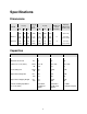
Specifications Dimensions Model Chamber Size in (cm) W D H Overall Size in (cm) Capacity feet3 (liters) W D H Maximum Number of Shelf Positions Exhaust Dimension inches (cm) LFD 1-42 20 (50) 18 20 (46) (51) 4.2 (120) 33 (84) 41 (104) 45 (114) 9 1.75 x 2.75 (4.5 x 7.0) LFD 2-11 38 (96) 20 26 (50) (66) 11.0 (310) 54 (137) 35 (88) 78 (198) 6 3.5 x 8.5 (8.9 x 21.6) LFD 2-24 48 (122) 24 36 (61) (91) 24.0 (680) 66 (166) 38 (98) 89 (226) 9 3.5 x 8.5 (8.9 x 21.
Temperature Model Time to Temperature (approximate minutes with no load) LFD 1-42 LFD 2-11 LFD 2-24 25°C - 100°C 25°C - 200°C 25°C - 343°C 4 10 35 4 10 30 2 10 40 100°C 200°C 343°C <1 2 4 <1 3 8 <1 3 7 100°C* 200°C* 343°C* ±1°C ±2°C ±4°C ±1°C ±2°C ±4°C ±1°C ±2°C ±4°C dampers open dampers closed 40°C 50°C 30°C 40°C 30°C 55°C Control Stability ±0.3°C ±0.3°C ±0.3°C Repeatability ±0.5°C ±0.5°C ±0.5°C 46 110 40 120 27 85 Recovery Time Door Open 1 Min.
Power Line voltages may vary in some geographical locations. If your line voltage is much lower than the oven voltage rating, warm up time will be longer and motors may overload or run hot. If your line voltage is higher than name plate rating, the motor may run hot and draw excessive amps. If the line voltage varies more than 10% from the oven voltage rating, some electrical components such as relays, temperature controls, etc. may operate erratically.
THEORY OF OPERATION This section details the function and operation of assemblies and subassemblies on the Despatch LFD Series Ovens. These ovens have the most effective heat distribution system and the fastest processing time of any lab ovens their size. They are especially useful for testing, preheating, sterilizing, drying, aging and curing as well as other production applications. Horizontal airflow with precision digital control delivers uniform, fast processing.
Damper Control The oven is equipped with a manually adjustable damper mechanism. The damper control arm is located on the front panel of the oven. The damper adjustment controls the flow of fresh air into the chamber. If the damper is in the full open position, the maximum amount of fresh air is distributed into the chamber. An additional adjustable damper is provided on the exhaust.
Full Open Position When the fresh air damper is in the full open position, the chamber will operate at its minimum operating temperature. Friction heat from the air recirculation system builds up in the chamber. This causes chamber temperature to rise slightly even though the heating system is not turned on. After the recirculation motor has been on for an extended period of time, the chamber will reach a thermal equilibrium temperature.
OVEN INSTRUCTIONS The INSTRUCTIONS section provides directions for unpacking, installation, operation and maintenance of the LFD Series oven. Unpacking and Inspection Remove all packing materials and thoroughly inspect the oven for damage of any kind that could have occurred during shipment. See whether the carton and plastic cover sheet inside carton are still in good condition. Look at all outside surfaces and corners of the oven for scratches and dents.
Set-up 1. Select the location for installing your oven. WARNING: If solvents are going to be used in the oven, you must install an exhaust stack to the outside of the building. Go to step 2. Do not use the oven in wet, corrosive or explosive atmospheres unless this oven is specifically designed for a special atmosphere. If no exhaust stack is necessary, go to step 3. 2. Install an exhaust stack from the rectangular exhaust fan discharge stack to the outside of the building.
Operating Users and operators of this oven must comply with operating procedures and training of operating personnel as required by the Occupational Safety and Health Act (OSHA) of 1970, Section 5 and relevant safety standards, and other safety rules and regulations of state and local governments. Refer to the relevant safety standards in OSHA and National Fire Protection Association (NFPA), Section 86 of 1990.
Pre-Startup Checklist Know the system. Read this manual carefully. Make use of its instructions and explanations. Safe, continuous, satisfactory, trouble-free operation depends primarily on your understanding of the system and your willingness to keep all parts in proper operating condition. Check line voltage. Voltage must correspond to nameplate requirements of motors and controls. Refer to the section on power connections in the INTRODUCTION of this manual. Fresh air and exhaust.
Note that in a Class A oven, the heater can not be energized until the forced exhaust system has brought in a minimum amount of fresh air into the chamber. The purge timer provided prevents the heater from energizing until the oven has had enough time to bring in the amount of fresh air required. The purge timer is energized by the airflow switch which closes when the exhaust system is running. The pre-determined purge time is two minutes for the LFD1-42 and LFD2-24 and three minutes for the LFD2-11.
CONTROL The special features of the Protocol PlusTM control include: PID tuning Ramp/Soak programming of up to 64 segments Segment looping and profile linking Built-in manual reset high limit control Built-in process timer Dedicated LED display for process temperature Multi-purpose two-line LCD display with backlight Auto-tuning Security access Process temperature retransmission signal Digital inputs for remote profile control Real time clock Optional relay outputs for events, alarms, or end-of-cycle signal
Protocol Plus Faceplate and Wiring Diagram 14
Operating Modes The Protocol Plus control has five modes of operation available: Stopped Mode: All control and relay outputs are off. Stopped Mode is integrated into each of the following four modes of operation. Manual Mode: Control operates as a single setpoint control until Stopped mode is accessed Timer Mode: Control operates as a single setpoint control until preset time period has expired. Profile Mode: Control operates as a ramp/soak profiling control until the end of the profile.
High Limit The control has an integrated high limit function which will disable the heater output when tripped. If the high limit does trip, the relay will need to be manually reset. When the high limit relay is tripped, the Hi-Limit indicator will be lit. Allow the oven to cool several degrees (or increase the high limit setpoint) and then press the Reset key. The indicator will turn off.
Displays The Protocol Plus control has two displays. A dedicated LED upper display shows the oven temperature. A two-line LCD lower display provides information on control status, high limit temperature, and allows changes to be made to the control settings. Key Functions The Protocol Plus control has seven keys that provide operation. Select key: Press to select mode of operation. In Setup Mode, to select profile number or relay.
Outputs The Protocol Plus control has seven different outputs available. Heating output: The control output is a DC voltage open-collector output which is time-proportioned and designed to control a heat control device such as a solid state relay. High limit: The high limit output is a form C relay which is energized under normal operating conditions.
Relay (Continued) Use the Relay Card Optional Ay p/n 144562 to add relays to the standard controller. Each relay card contains two relays (maximum of two cards Ay’s allowed). Communication The Protocol Plus control has optional MODBUS communication available which can communicate via RS232, RS422, or RS485 to a computer. See communications option assembly p/n 161957 for board and cable assembly. Please refer to the MODBUS communications manual which comes with this option.
INSTRUCTIONS Start-Up These instructions are provided as a quick reference for operating the Protocol Plus control. If the Profile Mode is to be used, or the configuration of the control needs to be changed, please refer to the Setup Mode instructions before operating the control. For more detailed operating instructions refer to the Operation instructions for the mode you wish to use. Upon initial power-up the control is in Manual/Stopped Mode (unless the Autostart or Fast Start Modes are active).
Operation Manual Mode Press the Select key until Manual is displayed (note you can press the Run key at any time to activate Manual Mode). 1. Press the Menu key to display the Process Temperature Setpoint (setpt). You can change the Setpoint with the keys. Note: If the SPChange parameter on the Enable page in Setup Mode has been set to DISABLED, it must be changed to ENABLED before any changes to the process temperature and high limit setpoints can be made. 2.
Timer Mode 1. Press the Select key until Timer is displayed (note you can press the Run key at any time to activate Timer Mode). 2. Press the Menu key to display the Process Temperature Setpoint (Setpt). You can change the Setpoint with the keys. Note that if the SPChange parameter on the Enable page in Setup Mode has been set to DISABLED, it must be changed to ENABLED before any changes to the process temperature and high limit setpoints can be made. 3.
Profile Mode 1. Press the Select key until Profile is displayed. “None” may be displayed if a profile has not been selected or no profiles entered. 2. Press the key to display the desired profile to run. 3. To start Profile Mode, press the Run key. The display will change from Stop to Run and the segment time remaining, Temperature Setpoint, Profile #, along with the current segment number, will be displayed. To return to Stopped Mode, press the Stop key.
Note that once you activate Auto Start, you can continue to use all operating modes as normal. If an operating mode is running at the time of a preset Auto Start function, and Auto Start is activated, the existing operating mode will override the auto Start function and the Auto Start will not turn on. Note: All process Set to Run in Auto Start Mode must be at least one minute long for all Run Modes (Manual, Timer, and Profile).
Instructions for Setup Mode Pages Program Page Programming of the profiles is provided on the Program Page. Eight profiles are available with up to eight ramp and soak segments per profile. If the optional relay outputs are installed, they must be configured as alarms or events on the Relay Outputs Page before they can be utilized. If configured as event outputs, these relays can be used as time or temperature events.
Menu Item Display Description Ramp Time Seg 1 Pro-1 Seg-1 Ramp Time Ramp time for segment 1 of profile Event 1 Set Value* Pro-1 Seg-1 Ramp Event 1 Event 1 setting for segment 1 ramp of profile Event 2 Set Value* Pro-1 Seg-1 Ramp Event 2 Event 2 setting for segment 1 ramp of profile Event 3 Set Value* Pro-1 Seg-1 Ramp Event 3 Event 3 setting for segment 1 ramp of profile Event 4 Set Value* Pro-1 Seg-1 Ramp Event 4 Event 4 setting for segment 1 ramp of profile Soak Temp Seg 1 Pro-1 Seg 1 So
Profile # There are eight profiles available. Segment# Recipe segments 1 through 8 may be programmed, each with its own set of events, ramp and soak times, and soak temperature. Ramp Time The time required to ramp from one setpoint up to another setpoint. Values between 0 and 99:59 are allowable. In the Protocol Plus controller, the profile ramp and soak times are stored without units. Units are set as either hours and minutes (HH:MM) or minutes and seconds (MM:SS).
Sample Profile Programming Table Profile Number____1______ Segment Time 1 Profile Name__________ Ramp Events 2 3 Soak 4 Temperature Time 1 01h00 100 01h00 2 02h00 50 00h01 3 00h00 4 5 6 7 8 High Limit Setpoint 115 Loop From Seg No Loop To Seg No Loop Number 0 Link To Pro No Guar Soak Band 10 28 Events 1 2 3 4
Auto Start Page The Auto Start Page can be configured to automatically start Manual, Timer or Profile Mode at a specified time and day. Note that if Auto Start Enable is set to Yes in the Setup Mode, the Auto Start feature is not turned on - it is available to the operator to be activated in Stopped Mode. To configure the Auto Start feature: 1. Access the Setup Mode. 2. Press the Page key until Auto Start is displayed. 3. Press the Menu key.
Menu Item Enable Autostart Sunday mode Sunday time Monday mode Monday time Tuesday mode Tuesday time Wednesday mode Wednesday time Thursday mode Thursday time Friday mode Friday time Saturday mode Saturday time Display Description Range Auto Start Enable Enable (yes) or disable (no) the Autostart function No, Yes Set mode on Sunday to activate Off, Manual, Timer, Pro-1 to Pro-8 Set time on Sunday for mode to activate 00:00 to 23:59 Set mode on Monday to activate Off, Manual, Timer, Pro-1 to Pro-
PID Page The PID Page contains parameters which control the response to the setpoint and process variable input. To access the PID Page, enter the Setup Mode. Press the Page key until PID is displayed. Press the Menu key. Each parameter can be changed by pressing the Menu key until the desired parameter is displayed, and then pressing the keys to change the value.
Control Page The Control Page contains various parameters which control miscellaneous functions. To access the Control Page, enter the Setup Mode. Press the Page key until Control is displayed. Press the Menu key. Each parameter can be changed by pressing the Menu key until the desired parameter is displayed, and then pressing the keys to change the value.
Communication Page (optional) The Communication Page contains parameters for the communications feature. To access the Communications Page, enter the Setup Mode (see description earlier in this manual). Press the Page key until Communication is displayed. Press the Menu key. (NOTE: If there is no change in the display, the controller does not have the communications board installed.
Relay Outputs Page (optional) The Relay Outputs Page configures the four alarm/event outputs. Each output has a dedicated indicator light and can be configured as a temperature alarm, profile event, or end of cycle output. Temperature alarms can be of type process high, process low, deviation high, deviation low, or deviation band. To access the Relay Page, enter the Setup Mode (see description earlier in this manual). Press the Page key until Relay is displayed.
Test Page The Test Page contains parameters which allow manual control of the heat control and optional relay outputs and should be used only for testing the functionality of the control instrument. Do not operate the oven for processes using the Test Page. To access the Test Page, enter the Setup Mode (see description earlier in this manual). Press the Page key until Test is displayed. Press the Menu key.
Zone Calibration Page The Zone Calibration Page allows adjustment of the displayed temperature versus the actual temperature measured by the control thermocouple. This may be desirable in certain conditions where the center of the oven chamber is not the same temperature as the control thermocouple. This may occur when the oven is not allowed to soak at a constant temperature for long periods of time, or the oven is being used at high temperature.
As an example, the control is displaying 400°F with the setpoint being 400°F, but the center of the oven chamber is actually 395°F. This can occur due to oven wall losses and product loading variations. The operator may change the zone calibration so that the center of the oven is 400°F when the display reads 400°F. In this case operate the oven in manual mode with a setpoint of 400°F. Record the center of the chamber (as measured with an independent sensor).
Sensor Calibration Page The Sensor Calibration Page has parameters which can change the internal calibration of the temperature sensor input signal. There is a low and high calibration point for both the control sensor and the high limit sensor. To calibrate the instrument, allow the control to warm up for at least 30 minutes. To access the Sensor Calibration Page, enter the Setup Mode (see description earlier in this manual). Press the Page key until Control Sensor is displayed. Press the Menu key.
19. Connect a calibration instrument with a type J thermocouple output to the control sensor input. 20. Connect a voltage measurement device to the retransmit output terminals. 21. Set the calibration instrument output to the temperature value of the RetOutLo parameter from the Control Page. 22. Adjust the RetCalLo * value using the keys until the voltage measurement device reads 1VDC. 23. Press the Menu key. 24.
Enable Page The Enable Page controls access to the other Setup Pages. The setpoint minimum and maximum values, and the security passwords are also set on the Enable Page. To access the Enable Page, enter the Setup Mode using a level 2 access code (see description earlier in this manual). Press the Page key until Enable is displayed. Press the Menu key. Each parameter can be changed by pressing the Menu key until the desired parameter is displayed, and then pressing the keys to change the value.
Digital Inputs (optional) The Protocol Plus control can be run by external inputs wired to the control from an external source such as a PLC or control panel switches. The external run operation can Run, Hold or Stop profiles 1 through 7 (profile 8 can not be operated externally). Refer to the table below for the inputs required for the desired operation. NOTE: A profile must be created in the program page before trying to run a profile number.
Error Messages and Alarms The Alarm Status Hi-limit LED is flashing. This indicates a problem with the thermocouple, or the Hi-limit setpoint has been exceeded. Once the problem has corrected, press the Reset pushbutton. The Alarm Status Soak LED is flashing. This indicates that the oven temperature has not entered or dropped out of the soak band and the soak timer has stopped. The top LED Display reads OPEN and the lower LCD display reads CONTROL SENS ERR.
Quick Reference and Default Values Program Page Menu Item Ramp Time Seg 1 Display Pro-1 Seg-1 Ramp Time Default 00:00 Event 1 Set Value Pro-1 Seg-1 Ramp Event 1 Off Range 00m00s to 99h59s Off, On Event 2 Set Value Pro-1 Seg-1 Ramp Event 2 Off Off, On Event 3 Set Value Pro-1 Seg-1 Ramp Event 3 Off Off, On Event 4 Set Value Pro-1 Seg-1 Ramp Event 4 Off Off, On Soak Temp Seg 1 Pro-1 Seg 1 Soak Temp 68°F Soak Time Seg 1 Pro-1 Seg 1 Soak Time 00:00 Event 1 Set Value Pro-1 Seg-1 Soak Eve
Programming Table Profile Number__________ Profile Name__________ Segment Time 1 Ramp Events 2 3 Soak 4 Temperature 1 2 3 4 5 6 7 8 High Limit Setpoint Loop From Seg Loop To Seg Loop Number Link To Pro Guar Soak Band 44 Time Events 1 2 3 4
Autostart Menu Item Enable Autostart Display Auto Start Enable Default No Range No, Yes Sunday mode Auto Start Sun Mode Off Sunday time Auto Start Sun Time 00:00 Off, Manual, Timer, Pro-1 to Pro-8 00:00 to 23:59 Monday mode Auto Start Mon Mode Off Monday time Auto Start Mon Time 00:00 Tuesday mode Auto Start Tue Mode Off Tuesday time Auto Start Tue Time 00:00 Wednesday mode Wednesday time Auto Start Wed Mode Off Auto Start Wed Time 00:00 Thursday mode Auto Start Thu Mode Off T
Control Menu Item Display Default Range Cycle Time Control Cycle Time 1 1 to 60 seconds Setting High limit setpoint Control Hi-Lim SP Max HiLimSP MinHiLimSP - MaxHiLimSP* High limit band Control Hi-Lim Band Off Off, 3°C to 11°C (5°F to 20°F) Power fail recovery Control PwrFRec Stop Stop, Restart, Hold, Resume Recovery time limit Control PwrFTime 00m00s 00m00s to 99m59s Powerup start enable Control EPwrStrt Dis Dis, En Powerup Start Mode Control StrtMode Off Off, Manual, Timer
Real Time Clock Menu Item Display Default Range Day of the week Clock Day Mon Time of day Clock HH:MM 00:00 Sun, Mon, Tue, Wed, Thu, Fri, Sat 00:00 to 23:59 Setting Reset clock Clock UP to Reset CLK* Ready Ready, Done * if the key is not pressed, the clock values will retain their original values, the display will change to Done if the clock is reset Relay Outputs (optional) Push Select key to select relay.
Test Menu Item Display Default Range Heater output Test HeatOut Off On High limit relay Test HiLimOut Off On Relay 1 output Test Rly1 Out Off On Relay 2 output Test Rly2 Out Off On Relay 3 output Test Rly3 Out Off On Relay 4 output Test Rly4 Out Off On High Limit Sensor Test HL Temp (sensor reading) Setting Zone Cal Menu Item Display Default Range Zone 1 actual Zone Cal Zone1Act 38°C Zone1 displayed Zone Cal Zone1Dis 38°C Zone 2 actual Zone Cal Zone2Act 260°C Zon
Enable Page Menu Item Display Default Range Profiles Enable Profile 1-8 Yes Yes or No Autostart Enable Auto Start No Yes or No ** PID Enable PID Yes Yes or No Control Enable Control No Yes or No Communication Enable Communication No Yes or No ** Real Time Clock Enable Clock No Yes or No ** Relay outputs Enable Relay 1-4 No Yes or No ** Test Enable Test No Yes or No Zone Calibration Enable Zone Cal No Yes or No Sensor Calibration Enable Sensor Cal No Yes or No Setp
Technical Specifications UL, cUL listed: UL file E136675 CE compliance to: EMC Directive 89-366/EEC European Standard EN55011/1991 European Standard EN50082-2/1995 Power supply: 100 to 240 VAC +10% -15%, 50-60Hz, 30VA Maximum 12 to 24 VAC/VDC +/-10%, DC to 60Hz, 30VA Maximum Temperature: Humidity: Storage -20 to 60°C Operating 0 to 50°C 90% or less, non-condensing Sensor inputs: Type J thermocouple -73°C to 760°C (-100°F to 1400°F) Input impedance 1M ohm or greater Common mode noise rejection of 14
Maintenance Do not attempt any service on this oven before opening the main power disconnect switch. Checklist Keep equipment clean. Gradual dirt accumulation retards air flow. A dirty oven can result in unsatisfactory operation such as unbalanced temperature in the work chamber, reduced heating capacity, reduced production, overheated components, etc. Keep the walls, floor and ceiling of the oven work chamber free of dirt and dust. Floating dust or accumulated dirt may produce unsatisfactory work results.
Tests Tests should be performed carefully and regularly. The safety of personnel as well as the condition of equipment may depend upon the proper operation of any one of the functions of the temperature control. Test the control every 40 hours. Check that the heater LED is cycling on and off, indicating that the heater is working. Also check the high limit function to make sure it is working properly. To test the high limit: 1.
Replacement Parts To order or return parts, contact the Service Products Division at Despatch. The Service Products features our Response Center for customer service. When returning parts, a Despatch representative will provide you with an MRA (Material Return Authorization) number. The MRA number must be attached to the returned part for identification. When you are ordering parts, be sure to give the model number, serial number and the part number.
Protocol Plus™ Instrument (Tools needed: 1/4" socket driver with #1 bit, #2 Phillips screwdriver) 1. Disconnect the power. 2. Remove the screws from the control panel and slide it forward. 3. Unplug all terminals on the rear of the control, noting the proper connections. 4. Remove the four retaining clips for the control. 5. Remove the control. 6. Insert the new control into the panel. 7. Fasten the four retaining clips. 8. Re-plug all terminals. 9. Fasten the control panel.
Fan Motor (Tools needed: Screwdriver, 5/32 inch Allen wrench, one quarter (¼) inch socket set) 1. Remove the chamber floor plate. a. Remove the screws from the floor plate. b. Lift the floor plate out of the oven. 2. Remove the left side wall. 3. Remove the fan inlet plate. 4. Loosen the set screws (2) on fan wheel in middle of oven bottom. You can reach the fan wheel by going through the heater or by disconnecting and removing the heater. Refer to the Heater Unit instructions. 5.
c. Reattach the motor lead wires to the terminal strip. 11. Replace the oven bottom (LFD1-42) or control panel front (LFD2-11 or 2-24). 12. Turn the oven right side up. 13. Adjust the fan wheel for 3/16 inch clearance between the wheel and the inlet ring. 14. Tighten the set screws on the fan wheel. 15. Check that the set screws hit the flats machined into the motor shaft. 16. Replace the chamber floor plate.
Troubleshooting Equipment which operates for long periods of time may develop problems. Below are possible problems and suggested solutions. If you have a problem not listed and do not know what to do, contact Despatch Industries at our toll free Help Line 800-473-7373. Difficulty Failure to heat Slow heat up Frequent heater element out Erratic temp. or inaccurate temp. Probable Cause No power Suggested Remedy Check power source and/or oven and wall fuses.
Difficulty Excess surface or door temp. Improper airflow Excessive vibration Oven will not control at setpoint Heater does not shut down until temp. reaches the Hi-limit setting Probable Cause Door seal deterioration Suggested Remedy Replace door seal. Fan motor failure Replace fan motor. Fan wheel seated too low on fan shaft Adjust fan wheel for 3/16" clearance between wheel and inlet ring. Unbalanced fan wheel Dirty fan wheel Replace fan wheel. Clean fan.
APPENDIX Temperature Scale Conversion (C/F) The Protocol Plus controller can be operated in either C or F. The default setting for the controller is C. Changing from one to the other is as follows: 1. Go into the Setup Mode on the controller. 2. Press the Select Key until Setup is displayed. 3. Press the Page key and Security will be displayed. 4. Press the Menu Key and Password will be displayed. Use the arrow keys to enter the proper password. The default password is 2 for level two. 5.
Optional MRC5000 Recorder Setup The temperature is retransmitted to the Recorder from the Controller. Set up the Recorder as follows: 1. Make sure that jumper JU1 is setup for the 5 VDC setting (see MRC Manual). 2. Move the Mode switch to the PROG/TEST/CAL position, and Prog will be displayed. 3. Press the down arrow key twice and Inps will be displayed. Make sure the settings are per the table below. 4. Once all the settings have been changed, move the Mode switch to the RUN position.