Protocol 3 Owner’s Manual Version 1.2 PREFACE 1 PROTOCOL 3™ Controller OWNER’S MANUAL E-105 PN 313327 VERSION 1.2 6/2013 Copyright © 2013 by Despatch Industries. All rights reserved.
Protocol 3 Controller Owner’s Manual Version 1.2 PREFACE 2 Revision History Revision 1.0 1.1 Date 1/2012 3/2013 Author K. Livingston K. Livingston 1.2 6/2013 K. Livingston Description Initial release Modified instructions for delayed start and remote communication. Modbus User’s Programming Manual added (E-106/ PN320813, Version 3/2013, Updated for Engineering Issue 8). Minor edits Copyright © 2013 by Despatch Industries. All rights reserved.
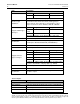
Protocol 3 Owner’s Manual Version 1.2 PREFACE 3 Table of Contents 1. About This Manual ................................................................................................. 6 1.1. Important User Information .......................................................................... 6 1.2. Manufacturer & Service ................................................................................ 7 1.3. Organization of this Manual ......................................................................
Protocol 3 Controller Owner’s Manual Version 1.2 PREFACE 4 6. 7. 8. 5.6.1.1. Access the Configuration Menu .......................................................... 49 5.6.1.2. Work with the Alarm Menu................................................................. 49 5.6.1.3. Using Alarms to Switch Relay Outputs ............................................... 50 5.6.1.4. Alarm Application Example ................................................................ 51 5.6.1.5. Glossary of Alarm Terms ....
Protocol 3 Owner’s Manual Version 1.2 PREFACE 5 Figure 17. USB Port on Front Panel. ................................................................................ 43 Figure 18. USB Files and Folders Requirements (as seen from Windows Explorer). ..... 43 Figure 19. Configuration Menu (see also Table 16 for more information). ..................... 46 Figure 4. How High, Low and Band process alarms are implemented. ........................... 53 Figure 20. Service Information Screen. ......................
Protocol 3 Controller Owner’s Manual Version 1.2 ABOUT THIS MANUAL 6 1. About This Manual 1.1. Important User Information Copyright © 2013 by Despatch Industries. All rights reserved.
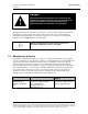
Protocol 3 Controller Owner’s Manual Version 1.2 ABOUT THIS MANUAL 7 Danger! Only fully-trained and qualified personnel should setup and maintain this equipment. Improper setup and operation of this equipment could cause an explosion that may result in equipment damage, personal injury or possible death. The information in this document is not intended to cover all possible conditions and situations that might occur.
Protocol 3 Controller Owner’s Manual Version 1.2 ABOUT THIS MANUAL 8 1.3. Organization of this Manual This owner’s manual contains the most comprehensive set of information for the Despatch Protocol 3™ controller, including installation instructions, theory of operation, operating instructions, among other things. Danger! Failure to heed warnings in this instruction manual and on the oven could result in personal injury, property damage or death. 1.4.
Protocol 3 Controller Owner’s Manual Version 1.2 ABOUT THIS MANUAL 9 1.5. Specifications Specifications for the Protocol 3 controller include six sets of information: Process Input (Table 1) Outputs (Table 2) Operating Conditions (Table 3) Conformance Norms (Table 4) Display (Table 5) Data Recorder (Table 6) Table 1. Process Input. Item Description Sampling Rate: 4 per second Resolution: 16 bits. Always four times better than display resolution.
Protocol 3 Controller Owner’s Manual Version 1.2 ABOUT THIS MANUAL 10 Item Description S 0 to 1762°C 32 to 3204°F T ‐240 to 400°C ‐400 to 752°F * Optional decimal place can be displayed up to 999.9°C/F Thermocouple Calibration: Supported RTD Types & Ranges: ±0.1% of full range, ±1LSD (±1°C for internal CJC if enabled). Linearization better than better ±0.2°C (±0.05 typical) on ranges marked * in the table above. Linearization for other ranges is better than ±0.5°C. BS4937, NBS125 & IEC584.
Protocol 3 Controller Owner’s Manual Version 1.2 Item ABOUT THIS MANUAL 11 Description Linear DC Resolution: 8 bits in 250mS (10 bits in 1s typical, >10 bits in >1s typical) Accuracy: ±0.25% of range, (mA @ 250W, V @ 2kW). Degrades linearly to ±0.5% for increasing burden (to specification limits) Isolation: Basic Isolation Table 3. Operating Conditions (For indoor use).
Protocol 3 Controller Owner’s Manual Version 1.2 ABOUT THIS MANUAL 12 Table 6. Data Recorder. Item Description Recording Memory: 1Mb non‐volatile flash memory. Data retained when power is turned off Recording Interval: 1; 2; 5; 10; 15; 30 seconds or 1; 2; 5; 10; 15; 30 minutes Recording Capacity: Dependent on sample rate and number of values recorded. Two values can be recorded for up to 7 days at 10s intervals. More values or faster sample rates deduce the maximum duration.
Protocol 3 Controller Owner’s Manual Version 1.2 2. Safety 2.1. Safety Information Do not work on the Protocol 3 controller without reading and understanding this section which contains important information and warnings. Ignoring these warnings can result in death, serious injury or damage to the machine and product. 2.1.1. Lockout Machine lockout places the Protocol 3 controller into a zero energy state and prevents accidental machine start up.
Protocol 3 Controller Owner’s Manual Version 1.2 SAFETY 14 2.3. Electrical Power Only qualified and trained personnel should perform electrical maintenance or electrical repair. Danger! Contact with energized electrical sources will result in serious injury or death. Before performing maintenance, disconnect all electrical power from the machine. Use a padlock and lockout all disconnects feeding power to the machine. Never clean or repair the controller when in operation.
Protocol 3 Controller Owner’s Manual Version 1.2 3. THEORY OF OPERATION 15 Theory of Operation The Protocol 3 is a microprocessor based digital temperature controller designed for simple and flexible oven operation (Figure 1). The Protocol 3 controller operates as a dual-functioning controller/high limit instrument. The control portion utilizes a time-proportioning voltage signal to control heating devices with minimal temperature fluctuations. Figure 1. Operator Interface.
Protocol 3 Controller Owner’s Manual Version 1.2 THEORY OF OPERATION 16 3.1.2. Outputs The Protocol 3 controller comes standard with an output signal that can transmit temperature data, setpoint data or control power to a user-supplied recording device. Output relays (five) can also signal user-specified events or alarm to external devices (Figure 2 and Figure 3).
Protocol 3 Controller Owner’s Manual Version 1.2 THEORY OF OPERATION 17 Figure 2. Typical Controller Output Sticker. Former SSR and Hi-Limit Connections Former Hi-limit Thermocouple Connections Former Power Connections Former Control Thermocouple Connections Protocol Plus Rear Panel New Control Thermocouple Connections Relays New SSR and Hi-Limit Connections New Power Connections New Hi-limit Thermocouple Connections Protocol 3 Rear Panel Figure 3.
Protocol 3 Controller Owner’s Manual Version 1.2 ASSEMBLY & SETUP 18 4. Assembly & Setup Danger! All grounding and safety equipment must be in compliance with applicable codes, ordinances and accepted safe practices. Warning! Disconnect the main power switch or power cord before attempting any repair or adjustment. 4.1. Install the Protocol 3 Controller When replacing a Protocol 3 controller, follow the steps below.
Protocol 3 Controller Owner’s Manual Version 1.2 ASSEMBLY & SETUP 19 4.3. Setting Up Remote Communication Remote communication between the Protocol 3 controller and a PC running the Despatch Protocol Manager software involves providing each controller with a unique address and following the communication protocol procedures. Up to 32 separate controllers can be run from a PC running the Despatch Protocol Manager software. See the Protocol Manager Instruction Manual for the complete set-up procedure.
Protocol 3 Controller Owner’s Manual Version 1.2 WORKING WITH OPERATING MODES 20 5. Working with Operating Modes Users and operators of this controller must comply with operating procedures and training of operating personnel as required by the Occupational Safety and Health Act (OSHA) of 1970, Section 5 and relevant safety standards, and other safety rules and regulations of state and local governments.
Protocol 3 Controller Owner’s Manual Version 1.2 Keypad Button WORKING WITH OPERATING MODES 21 Function Navigate to previous screen Press to move back to the previous parameter or screen in the current mode. NOTE: Pressing this switch updates the instrument to the value displayed. If editing a parameter, ensure the current (highlighted) parameter value is correct before pressing.
Protocol 3 Controller Owner’s Manual Version 1.2 WORKING WITH OPERATING MODES 22 Keypad Button Function not in the High Alarm State (LED indicator turned OFF). Simultaneously press and to move up one menu level: From Select a Mode, pressing both moves to the main menu. From Sub-menus, press both several times to reach the main menu. NOTE: Simultaneously pressing these switches updates the instrument to the value displayed.
Protocol 3 Controller Owner’s Manual Version 1.2 LED WORKING WITH OPERATING MODES 23 Function Cycle Complete LED: When lit, indicates the controller is currently stopped. When lit during a profile or Timer Mode, indicates process value has deviated from the soak value indicated by the controller. Set Soak Deviation value in the Profile Configuration mode or in the Timer Mode from the Main Menu. See Troubleshooting Section 7 for more information.
Protocol 3 Controller Owner’s Manual Version 1.2 WORKING WITH OPERATING MODES 24 5.2.1. Manual Mode allows the oven to operate continuously at a fixed temperature until turned off. Use Manual Mode (Figure 5) to control Set Point, High Limit Value and four relays. Manual Mode Four relay LEDs Relay navigational boxes Figure Manual Mode Display Screen. Better 5. explanation: 5.2.1.1. Display Manual Mode From the Select a Mode screen, press the highlighted option. Press 5.2.1.2.
Protocol 3 Controller Owner’s Manual Version 1.2 WORKING WITH OPERATING MODES 25 b. After pressing , press to return to Select a Mode screen 7. Adjust the temperature setpoint while running in Manual or Timer Mode by: a. Press . b. Press or c. Press . d. Press or e. Press to select mode of operation. to change the SP value. . f. Press to return to normal display. 8. Return to Stopped Mode at any time, press and the Cycle Complete LED will illuminate Press to select a mode screen. 5.2.2.
Protocol 3 Controller Owner’s Manual Version 1.2 WORKING WITH OPERATING MODES 26 b. Press or c. Press . d. Press or e. Press . to navigate to the desired time or temperature units. to change the SP value. f. Press to return to normal display. 10. To return to Stopped Mode at any time, press illuminate. 11. Press and the Cycle Complete LED will to return to Select A Mode screen. 5.2.3. Profile Mode Navigate to HLSP to set the High Limit Setpoint before running a profile.
Protocol 3 Controller Owner’s Manual Version 1.2 WORKING WITH OPERATING MODES 27 Status bar shows status of profile and segment. Figure 7. Profile Mode. If you are unable to select a desired profile, verify that Remote Profile Control is Disabled. When Remote Profile Control is Disabled, the Select Profile to Start reads “Digital” 5.2.4. Main Menu The Main Menu (Figure 8) provides access to a number of useful sub menus (Table 10). Access the Main Menu from the Select a Mode screen (Figure 4) by: 1.
WORKING WITH OPERATING MODES 28 Protocol 3 Controller Owner’s Manual Version 1.2 Figure 8. Main Menu. Table 10. Sub Menu Descriptions Menu Item Description Mode Selection Return to Select a Mode screen Timer Mode See Timer Mode Option (Section 5.2.2) Profile Setup Create, edit and delete profiles Recorder Control Start, stop and delete recordings on unit.
Protocol 3 Controller Owner’s Manual Version 1.2 WORKING WITH OPERATING MODES 29 5.3. Setting up a Profile Regularly backup critical system data according to your company policies. Be sure to back up configuration and profiles to a removable memory device. Refer to Section 5.5.1 for more information. Use Profile Setup to create, edit and delete profiles (Figure 9). Access the Profile Setup from the Main Menu screen.
WORKING WITH OPERATING MODES 30 Protocol 3 Controller Owner’s Manual Version 1.2 Table 11. Profile Setup Options.
Protocol 3 Controller Owner’s Manual Version 1.2 WORKING WITH OPERATING MODES 31 Figure 10. Profile Setup Menu. Copyright © 2013 by Despatch Industries. All rights reserved. No part of the contents of this manual may be reproduced, copied or transmitted in any form or by any means including graphic, electronic, or mechanical methods or photocopying, recording, or information storage and retrieval systems without the written permission of Despatch Industries, unless for purchaser's personal use.
Protocol 3 Controller Owner’s Manual Version 1.2 WORKING WITH OPERATING MODES 32 Table 12. Profile Setup Steps, Options and Descriptions. Step # Protocol 3 Descriptor Option Description General Configuration Disabled Disallow a remote source to run a profile 1. Remote Profile Control Enabled Allow a remote source to run a profile Disabled Disallow use of delayed start time Automatic Start 2.
Protocol 3 Controller Owner’s Manual Version 1.2 Step # Protocol 3 Descriptor 11. 12. 13.
WORKING WITH OPERATING MODES 34 Protocol 3 Controller Owner’s Manual Version 1.2 Table 12 will serve as a useful guide for both general configuration and setting up a profile. Before initiating the Profile Setup, use the programming worksheet (Section 8.3) to work out all parameters. Once the Profile Setup is begun, setup must continue to the end or lose all entered values.
Protocol 3 Controller Owner’s Manual Version 1.2 WORKING WITH OPERATING MODES 35 5.3.2. Sample Profile Figure 11shows a graphic representation of the sample profile, while Figure 12 shows the parameters entered to achieve that profile. Section 5.3.3 shows how to enter the profile. Figure 11. Sample Profile. Copyright © 2013 by Despatch Industries. All rights reserved.
Protocol 3 Controller Owner’s Manual Version 1.2 WORKING WITH OPERATING MODES 36 Figure 12. Sample Profile Values. Copyright © 2013 by Despatch Industries. All rights reserved. No part of the contents of this manual may be reproduced, copied or transmitted in any form or by any means including graphic, electronic, or mechanical methods or photocopying, recording, or information storage and retrieval systems without the written permission of Despatch Industries, unless for purchaser's personal use.
Protocol 3 Controller Owner’s Manual Version 1.2 WORKING WITH OPERATING MODES 37 5.3.3. Key In the Sample Profile Setup To help show the process of setting up a profile, this section uses the sample profile as an example (from Figure 11 and Figure 12). Figure 10 shows the overall flowchart for working with Profile Setup. For entering sample values, we choose the default values. Navigate to and Enter Profile Setup From Select a Mode screen, simultaneously press and to display the Main Menu: 1.
Protocol 3 Controller Owner’s Manual Version 1.2 WORKING WITH OPERATING MODES 38 b. Press as needed to complete the entry. 17. For Auto-Hold Type, when None is highlighted, press 18. For Event 1-5, press to complete the entry. as needed to accept Inactive. Program Segment 2 according the Sample Profile: 19. When Segment Number 2 displays, press 20. Highlight Dwell and press 21. For Dwell at 100.0°C (212 °F), a. Press or b. Press . . navigate to 1 hour (01:00:00).
Protocol 3 Controller Owner’s Manual Version 1.2 WORKING WITH OPERATING MODES 39 a. For Segment End Type, with Control Off highlighted, press 32. For Profile Created, press 33. Press and and press . . to display the Main Menu. Press or to select Mode Selection . Table 13. Profile Parameter Options. Options Profile Parameter Number of profiles = 64 maximum. Profile Limits Total number of segments (all programs) = 255 maximum. 1 to 9999 loops back to specified segment.
Protocol 3 Controller Owner’s Manual Version 1.2 WORKING WITH OPERATING MODES 40 5.4. Recorder Control Use Recorder Control to start, stop and clear recordings (Figure 13). Access the Recorder Control from the Main Manu. 1. Navigate to and highlight Recorder Control. 2. Press to display Recorder Control Enter Data Recorder Unlock Code screen. 3. Press as necessary to enter Factory Unlock Code 0010. 4. Press Figure 13. Recorder Control. to display the Start/Stop Data Recording screen. 5.
Protocol 3 Controller Owner’s Manual Version 1.2 WORKING WITH OPERATING MODES 41 5.5. USB Menu Use USB Menu to perform read/write options for USB devices connected to the unit using the front USB port (Figure 15). Access the USB Menu from the Main Menu. See Table 14 for USB Menus options. Regularly backup critical system data according to your company policies. Be sure to back up configuration and profiles to a removable memory device. Refer to Section 5.5.1 for more information.
WORKING WITH OPERATING MODES 42 Protocol 3 Controller Owner’s Manual Version 1.2 Table 14. USB Menu Options.
Protocol 3 Controller Owner’s Manual Version 1.2 WORKING WITH OPERATING MODES 43 5.5.1. Working with USB Memory Stick Folders and Files Insert a memory stick into the port on the front panel (Figure 16). The Protocol 3 performs an initialization process that finds and/or creates folders on the memory stick (Figure 17): DEVICE: This folder must be located in the Root of the USB memory stick CONFIG: Configuration files (*.bct) PROFILE: Profile program files (*.
Protocol 3 Controller Owner’s Manual Version 1.2 WORKING WITH OPERATING MODES 44 5.5.2. File Naming Conventions The Protocol 3 controller names the first recorder log file 000001‐1.csv. Each time the recording parameters are changed, a new file is created. For instance, changing the recording parameters two times would produce these file names: 000002-1.csv 000003-1.csv Note that: Stopping or starting a recording does not create a new file.
Protocol 3 Controller Owner’s Manual Version 1.2 WORKING WITH OPERATING MODES 45 5.6. Configuration Menu Configuration provides access to menus that allow for setting up 11 different options: 1. Input: Input settings and calibrate for process and High Limit Inputs 2. Control 3. Output 4. Alarm 5. Power Fail Recovery 6. Comms. (Communication) 7. Recorder 8. Clock 9. Display 10. Lock Code Configuration 11.
Protocol 3 Controller Owner’s Manual Version 1.2 WORKING WITH OPERATING MODES 46 Figure 18. Configuration Menu (see also Table 15 for more information). Copyright © 2013 by Despatch Industries. All rights reserved.
Protocol 3 Controller Owner’s Manual Version 1.2 WORKING WITH OPERATING MODES 47 Table 15. Configuration Menu in Tabular Format. ConfigDescription Function Available Settings uration Menu Input Type: Thermocouples, PtRh, PT100, NI120, amperages, voltages Engineering Units: °C, °F, °K, bar, %, %RH, pH, psi or none Control Input Decimal Point Position: Nearest 1/10 or 1/100 Setup for DC inputs Scale Input Range (lower and upper limits): Min & Max range. Minimum range by default.
Protocol 3 Controller Owner’s Manual Version 1.2 WORKING WITH OPERATING MODES 48 Configuration Menu Output Alarm Power Fail Recovery Description Function Available Settings Set rate of change toward Segment Target Setpoint Output Configuration Output [1-5] Usage: Set Alarm, Event, Cycle Complete, Running, or combinations Linear Output Usage: Set the desired type for any Linear Outputs fitted. From: 0-5, 0-10, 1-5, 210V & 0-20, 4-20mA or 0-10VDC adjustable Transmitter PSU.
Protocol 3 Controller Owner’s Manual Version 1.2 WORKING WITH OPERATING MODES 49 5.6.1. Alarm Configuration 5.6.1.1. Access the Configuration Menu Access the Protocol 3 controller Configuration Menu,(and sub-menus) by first ensuring the controller is in Cycle Complete state (that is, not running), the control must be in its cycle complete state (not running), if it is in that state 1. Press to stop the control before proceeding. 2. Simultaneously press and from Select a Mode to access the Main Menu.
Protocol 3 Controller Owner’s Manual Version 1.2 WORKING WITH OPERATING MODES 50 Alarm Selection Process Low PV-SP Deviation Band Signal Change Per Min Input Signal Break Control Loop % Memory Used 5.6.1.3.
Protocol 3 Controller Owner’s Manual Version 1.2 5.6.1.4. WORKING WITH OPERATING MODES 51 Alarm Application Example This alarm example configures the Protocol 3 controller for an application with an external alarm horn wired into Relay 1. The horn should sound if the process value temperature drops two degrees below or rises five degrees above the setpoint temperature of 200 degrees. 1. Access the Configuration Menu by following the directions in Section 5.6.1.1 Accessing Configuration Menu. 2.
Protocol 3 Controller Owner’s Manual Version 1.2 WORKING WITH OPERATING MODES 52 5.6.1.5. Glossary of Alarm Terms Term Description Alarm Hysteresis Alarm hysteresis is the deadband on the safe side of an alarm (that is, the side of the alarm that is below the high alarm value or above the low alarm value). The signal must pass through this deadband before the alarm deactivates. Alarm Inhibit prevents unwanted process or deviation alarm activation at powerup or when the controller setpoint is changed.
Protocol 3 Controller Owner’s Manual Version 1.2 WORKING WITH OPERATING MODES 53 Figure 19. How High, Low and Band process alarms are implemented. Copyright © 2013 by Despatch Industries. All rights reserved.
Protocol 3 Controller Owner’s Manual Version 1.2 WORKING WITH OPERATING MODES 54 5.6.2. Working with Calibration Offsets Calibration offsets allow configuration for oven temperature variations. Enter calibration offsets through the Configuration Menu and Input Configuration. 5.6.2.1. Access the Configuration Menu To access the Configuration Menu and all sub-menus, the controller must be in its Cycle Complete or Stopped state (that is, not running).
Protocol 3 Controller Owner’s Manual Version 1.2 5.6.2.3. WORKING WITH OPERATING MODES 55 Factory Calibration Factory Calibration means there is no calibration offset. Selecting Factory Calibration disables the Single Point Calibration and Two Point Calibration options. There are no settings to configure for Factory Calibration. 5.6.2.4. Single Point Calibration The Single Point Calibration screen shows the current value by which the process input (PV) is offset.
Protocol 3 Controller Owner’s Manual Version 1.2 WORKING WITH OPERATING MODES 56 If the display on the control read 200 °C and the actual temperature measured was 195°C Enter the following settings for Two Point Calibration: o Calibration Low Temp = 100, Calibration Low Offset = -1 o Calibration High Temp = 200, Calibration High Offset = -5 Return to the Main Menu by simultaneously pressing and . 5.6.3.
Protocol 3 Controller Owner’s Manual Version 1.2 Auto Pre-Tune WORKING WITH OPERATING MODES 57 If active, Pre‐tune will attempt to run at every power up. Automatic tuning will not engage if proportional band is set to ON/OFF control. Pre‐tune and Auto Pre‐Tune will not engage if the setpoint is ramping or the Process Variable is < 5% of span from setpoint. 5.8. Product Information Access Product Information through the Main Menu (Section 5.2.4).
Protocol 3 Controller Owner’s Manual Version 1.2 WORKING WITH OPERATING MODES 58 Figure 20. Service Information Screen. 5.10. Remote Operation The Protocol 3 controller is equipped for remote operation using the Despatch Protocol Manager software. A PC running Despatch Protocol Manager software can access, operate and log data for up to 32 Protocol 3/Protocol Plus-equipped ovens. See the Protocol Manager Instruction Manual for complete operation instructions. Copyright © 2013 by Despatch Industries.
Protocol 3 Controller Owner’s Manual Version 1.2 WORKING WITH OPERATING MODES 59 5.11. Setting Up Digital Inputs The Protocol 3 controller can be run by external inputs wired to the controller from an external source such as a PLC or switches on a control panel (Figure 21 displays standard digital input wiring). Figure 21. Standard Digital Input Wiring. Enable Digital Inputs through the Profile Menu, then General Configuration and set Remote Profile Control to Enable.
Protocol 3 Controller Owner’s Manual Version 1.2 WORKING WITH OPERATING MODES 60 Input 1 Input 2 Input 3 Index Selection ON OFF ON 5 OFF ON ON 6 ON ON ON 7 OFF OFF OFF none Input 4 controls the action of the selected profile in the following way: Switch from OFF to ON to Start the selected profile or continue the profile if it is currently in Hold. Switch from ON to OFF to Hold a profile that is running.
Modbus Programming Manual Version 1.2 6. MAINTENANCE 61 Maintenance 6.1. Replacement Parts To order or return parts, contact the Despatch Global Service Network. The Service Products features our Response Center for customer service. When returning parts, a Despatch representative will provide you with an RMA (Return Material Authorization) number. Attach the RMA number to the returned part for identification.
Protocol 3 Controller Owner’s Manual Version 1.2 TROUBLESHOOTING 62 7. Troubleshooting 7.1. Error Messages and Alarm Table 20 lists the more common error messages, the possible problems and remedies. Table 20. Error Messages and Next Steps. Alarm Status Possible Problem Hi-Limit LED ON Problem with thermocouple Hi-limit setpoint has been exceeded.
Protocol 3 Controller Owner’s Manual Version 1.2 TROUBLESHOOTING 63 Review the Protocol Manager manual for specific tips and techniques for troubleshooting communication problems Figure 22. Check Cabling. Copyright © 2013 by Despatch Industries. All rights reserved.
Protocol 3 Controller Owner’s Manual Version 1.2 TROUBLESHOOTING 64 Figure 23. Older model serial converter schematic. Copyright © 2013 by Despatch Industries. All rights reserved. No part of the contents of this manual may be reproduced, copied or transmitted in any form or by any means including graphic, electronic, or mechanical methods or photocopying, recording, or information storage and retrieval systems without the written permission of Despatch Industries, unless for purchaser's personal use.
Protocol 3 Controller Owner’s Manual Version 1.2 TROUBLESHOOTING 65 Figure 24. Newer model serial converter schematic. Copyright © 2013 by Despatch Industries. All rights reserved. No part of the contents of this manual may be reproduced, copied or transmitted in any form or by any means including graphic, electronic, or mechanical methods or photocopying, recording, or information storage and retrieval systems without the written permission of Despatch Industries, unless for purchaser's personal use.
Protocol 3 Controller Owner’s Manual Version 1.2 TROUBLESHOOTING 66 Figure 25. USB Converter Schematic. . Copyright © 2013 by Despatch Industries. All rights reserved. No part of the contents of this manual may be reproduced, copied or transmitted in any form or by any means including graphic, electronic, or mechanical methods or photocopying, recording, or information storage and retrieval systems without the written permission of Despatch Industries, unless for purchaser's personal use.
Protocol 3 Controller Owner’s Manual Version 1.2 8. APPENDICES 67 Appendices 8.1. Standard Products Warranty Copyright © 2013 by Despatch Industries. All rights reserved. No part of the contents of this manual may be reproduced, copied or transmitted in any form or by any means including graphic, electronic, or mechanical methods or photocopying, recording, or information storage and retrieval systems without the written permission of Despatch Industries, unless for purchaser's personal use.
Protocol 3 Controller Owner’s Manual Version 1.2 APPENDICES 68 8.2. Modbus Programming For information on Modbus programming, refer to the Despatch web page (www.despatch.com) to search for and download the “Modbus Programming Manual” version 3 (Rev 3/13) or later. 8.3. Programming Worksheet See Section 5.3 for help with completing Programming Worksheet (Table 21). Table 21. Programming Worksheet.
Protocol 3 Controller Owner’s Manual Version 1.2 APPENDICES 69 Copyright © 2013 by Despatch Industries. All rights reserved. No part of the contents of this manual may be reproduced, copied or transmitted in any form or by any means including graphic, electronic, or mechanical methods or photocopying, recording, or information storage and retrieval systems without the written permission of Despatch Industries, unless for purchaser's personal use.