Modbus Programming Manual Version 2 PREFACE 1 Modbus User’s Programming Manual for Protocol 3™ E-106 PN 320813 VERSION 2 7/2012 Copyright © 2012 by Despatch Industries. All rights reserved.
PREFACE 2 Modbus Programming Manual Version 2 Revision History Revision 1 Date 6/2012 Author Livingston 2 7/2012 Livingston Description Original Release - Revised for Protocol 3 and formatting Updated Register tables for new Protocol 3 Firmware release 2.0 Copyright © 2012 by Despatch Industries. All rights reserved.
Modbus Programming Manual Version 2 PREFACE 3 Table of Contents 1. About This Manual ............................................................................................................. 5 1.1. Important User Information ..................................................................................... 5 1.2. Manufacturer & Service .......................................................................................... 5 1.3. Organization of this Manual .......................................
PREFACE 4 Modbus Programming Manual Version 2 2.8.3. Timer Mode Parameters .................................................................................... 33 2.8.4. Profile Mode Parameters ................................................................................... 34 2.9. Uploading and Downloading of Profiles ............................................................... 35 2.9.1. Instruction Sequence to create a profile at the next available position .............. 36 2.9.2.
Modbus Programming Manual Version 2 1. ABOUT THIS MANUAL 5 About This Manual 1.1. Important User Information Copyright © 2012 by Despatch Industries. All rights reserved. No part of the contents of this manual may be reproduced, copied, or transmitted in any form or by any means including graphic, electronic, or mechanical methods or photocopying, recording, or information storage and retrieval systems without the written permission of the publisher, unless it is for the purchaser's personal use.
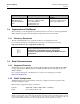
ABOUT THIS MANUAL 6 Modbus Programming Manual Version 2 Global Headquarters Contact Despatch Industries 8860 207th Street Lakeville, MN 55044 USA International/Main: 1-952-469-5424 US toll free: 1-888-337-7282 Fax: 1-952-469-4513 info@despatch.com www.despatch.com Service & Technical Support Service: 1-952-469-8230 US toll free: 1-800-473-7373 Service @despatch.com 1.3.
Modbus Programming Manual Version 2 Character format: Device Address: ABOUT THIS MANUAL 7 Always 8 bits per character. See below. 1.4.3. RS485 Device Addressing The instrument must be assigned a unique device address in the range 1 to 255. This address is used to recognize Modbus Queries intended for this instrument. With the exception of globally addressed broadcast messages, the instrument ignores Modbus Queries that do not match the address that has been assigned to it.
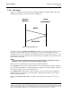
ABOUT THIS MANUAL 8 Modbus Programming Manual Version 2 1.4.5. Link Layer A Query (or command) is transmitted from the Modbus Master to the Modbus Slave. The slave instrument assembles the reply to the master (see Figure 1). MODBUS MASTER SLAVE INSTRUMENT QUERY RESPONSE Figure 1. Modbus Link Layer. A message for either a QUERY or RESPONSE is made up of an inter-message gap followed by a sequence of data characters. The inter-message gap is at least 3.
Modbus Programming Manual Version 2 Inter-message gap ABOUT THIS MANUAL 9 Address 1 character Function 1 character Data n characters CRC Check 2 characters 1.4.6. Supported Modbus Functions Modbus defines several function types.
ABOUT THIS MANUAL 10 Modbus Programming Manual Version 2 Function 06 - Write Single Register Writes two bytes to a specified word address. QUERY Function Address of Word 06 HI Value to write LO HI LO RESPONSE Address of Word Function 06 HI Value written LO HI LO Note: The Response normally returns the same data as the Query.
Modbus Programming Manual Version 2 ABOUT THIS MANUAL 11 Function 23 Hex - Read / Write Multiple Registers (0x17 hex) Reads and writes the requested number of consecutive words (two-bytes) starting at the specified addresses.
ABOUT THIS MANUAL 12 Modbus Programming Manual Version 2 The Modbus parameter register addresses are detailed in the following sections. The Access column indicates if a parameter is read only (RO) or if it can also be written to (R/W). Note: Some parameters that do not apply for a particular configuration will accept reads and writes. Read only parameters will return an exception if an attempt is made to write values to them. 1.4.8.
Modbus Programming Manual Version 2 ADDRESS LIST 13 2. Modbus Address List 2.1. Input Parameters 2.1.1.
ABOUT THIS MANUAL 14 Parameter Name Filter time constant Process Input Process Variable Process Input Sensor Break Flag Process Input Under Range Flag Process Input Over Range Flag Process Input CJC Enable Process Input User Calibration Type Process Input Low Temperature Calibration Point Process Input Low Calibration Offset Process Input High Temperature Calibration Point Process Input High Calibration Offset Modbus Programming Manual Version 2 Modbus Address (Dec) Modbus Address (Hex) Access R/W No
Modbus Programming Manual Version 2 ADDRESS LIST 15 Parameter Name Modbus Address (Dec) Modbus Address (Hex) Access R/W Notes 22 24 28 30 34 35 36 37 38 39 40 41 High Limit Input Engineering units 9001 0x2329 R/W High Limit Input Decimal Place 9002 0x232C R/W High Limit Input Range Minimum High Limit Input Range Maximum High Limit User Calibration Type 9003 0x232A R/W 9004 0x232B R/W 9008 0x2330 R/W High Limit Input Process variable offset Process Input Low Calibration Offset Proce
ABOUT THIS MANUAL 16 Parameter Name Modbus Programming Manual Version 2 Modbus Address (Dec) Modbus Address (Hex) Access R/W status Notes Bit 1 = Low Bit 2 = High 2.1.3. Digital Inputs Parameter Name Digital input states Modbus Address (Dec) 2001 Modbus Address (Hex) 0x7D1 Access R/W R Notes Bit Position 0 1 2 3 Digital input 1 2 3 4 2.2. Output Parameters 2.2.1.
Modbus Programming Manual Version 2 ADDRESS LIST 17 Parameter Name Modbus Address (Dec) Modbus Address (Hex) Access R/W Notes 3 Event Alarm Selection 2150 0x0866 R/W Value 0 1 2 3 4 Alarm 1 or Alarm 2 or Alarm 3 or Alarm 4 or Alarm 5 Selection Alarm 1 or Event 1 Alarm 2 or Event 2 Alarm 3 or Event 3 Alarm 4 or Event 4 Alarm 5 or Event 5 2.2.2.
ABOUT THIS MANUAL 18 Modbus Programming Manual Version 2 2.2.3.
Modbus Programming Manual Version 2 ADDRESS LIST 19 Parameter Name Modbus Address (Dec) Modbus Address (Hex) Access R/W Notes 1 2 3 4 5 6 7 8 9 10 11 12 13 14 Alarm Selection 2207 0x089F R/W Value 0 1 2 3 Event Alarm Selection 2209 0x08A1 R/W Value 0 1 2 3 4 Alarm 1 Alarm 2 Alarm 3 Alarm 4 Alarm 5 Event 1 Event 2 Event 3 Event 4 Event 5 Cycle Complete Profile Running Or of Alarms Alarm and Events Selection Alarm 1 or Alarm Alarm 1 or Alarm Alarm 1 or Alarm Alarm 4 Alarm 1 or Alarm Alarm 4
ABOUT THIS MANUAL 20 Parameter Name Modbus Programming Manual Version 2 Modbus Address (Dec) Modbus Address (Hex) Access R/W Notes 11 12 13 14 Alarm Selection 2218 0x08AA R/W Value 0 1 2 3 Event Alarm Selection 2220 0x08AC R/W Value 0 1 2 3 4 Cycle Complete Profile Running Or of Alarms Alarm and Events Selection Alarm 1 or Alarm Alarm 1 or Alarm Alarm 1 or Alarm Alarm 4 Alarm 1 or Alarm Alarm 4 or Alarm 2 2 or Alarm 3 2 or Alarm 3 or 2 or Alarm 3 or 5 Selection Alarm 1 or Event 1 Alarm 2
Modbus Programming Manual Version 2 ADDRESS LIST 21 2.3. Setpoint Parameters Parameter Name Setpoint Minimum Setpoint Maximum Manual/Timer Mode Setpoint Value Modbus Address (Dec) 3944 3945 Modbus Address (Hex) 0x0F68 0x0F69 Access R/W Notes R/W R/W Limited by input range maximum/minimum Limited by input range maximum/minimum 3960 0x0F78 R/W Limited by Setpoint maximum/minimum Copyright © 2012 by Despatch Industries. All rights reserved.
ABOUT THIS MANUAL 22 Modbus Programming Manual Version 2 2.4.
Modbus Programming Manual Version 2 ADDRESS LIST 23 Parameter Name Auto Pre-tune Modbus Address (Dec) 4336 Modbus Address (Hex) 0x10F0 Access R/W Notes R/W 0 = Disabled 1 = Enabled Copyright © 2012 by Despatch Industries. All rights reserved.
ABOUT THIS MANUAL 24 Modbus Programming Manual Version 2 2.5. Alarm Parameters 2.5.1.
Modbus Programming Manual Version 2 ADDRESS LIST 25 Parameter Name Modbus Address (Hex) 0x1815 Access R/W Notes R 0 = Not inhibited 1 = Inhibited Modbus Address (Hex) 0x1820 Access R/W Notes Alarm Type Modbus Address (Dec) 6176 R/W Alarm Value 6177 0x1821 R/W Alarm Hysteresis Alarm inhibit 6178 6179 0x1822 0x1823 R/W R/W Alarm status 6180 0x1824 R Alarm inhibit status Rate Minimum Time Alarm Value 6181 0x1825 R 0 = High Alarm 1 = Low Alarm 2 = Deviation Alarm 3 = Band Alarm 4
ABOUT THIS MANUAL 26 Parameter Name Modbus Programming Manual Version 2 Modbus Address (Dec) Modbus Address (Hex) Access R/W Notes alarms 4 and 5.
Modbus Programming Manual Version 2 ADDRESS LIST 27 Parameter Name Alarm Hysteresis Alarm status Modbus Address (Dec) 9023 9007 Modbus Address (Hex) 0x233F 0x232F Access R/W Notes R/W R Limited by the span of the input range 0 = Inactive 1 = Active Copyright © 2012 by Despatch Industries. All rights reserved.
ABOUT THIS MANUAL 28 Modbus Programming Manual Version 2 2.6. Logger parameters (Data Logger) 2.6.1.
Modbus Programming Manual Version 2 ADDRESS LIST 29 2.7. Display Parameters 2.7.1.
ABOUT THIS MANUAL 30 Modbus Programming Manual Version 2 2.7.4.
Modbus Programming Manual Version 2 ADDRESS LIST 31 Parameter Name Contact Details line 1 Contact Details line 2 Contact Details line 3 Contact Details line 4 Contact Details line 5 Contact Details line 6 Contact Details line 7 Communications Address Communications Baud rate Communications Parity Modbus Address (Dec) Modbus Address (Hex) Access R/W Notes 400 0x0190 R/W equipment 26 characters of text 401 0x0191 R/W 26 characters of text 402 0x0192 R/W 26 characters of text 403 0x0193
ABOUT THIS MANUAL 32 Modbus Programming Manual Version 2 2.8. Mode Controls 2.8.1.
Modbus Programming Manual Version 2 ADDRESS LIST 33 Parameter Name Manual Mode Relay 4 Modbus Address (Dec) 8252 Modbus Address (Hex) 0x203C Access R/W Notes R/W 0 = Off 1 = On 2.8.3.
ABOUT THIS MANUAL 34 Modbus Programming Manual Version 2 2.8.4.
Modbus Programming Manual Version 2 ADDRESS LIST 35 Parameter Name Profile Control Active Profile Name Profile Status Modbus Address (Dec) 8245 Modbus Address (Hex) 0x2035 Access R/W Notes R/W 8259 0x2043 R 0 = Do Nothing 1 = Run the selected profile 2 = Hold the currently running profile 3 = Abort the currently running profile 4 = Jump to the next segment 5 = Release a held profile 6 = Exit the profile control once the profile has completed and is holding the last setpoint The currently selec
ADDRESS LIST 36 Modbus Programming Manual Version 2 Command Code RS PN PS Value Decimal 21075 20558 20563 Value Hex 0x5253 0x504E 0x5053 Function Read Segment Read Profile Name Read the profiler memory status The following rules apply when creating a profile over communications: Profiles must always be terminated with an end segment. Segments cannot be added after an end segment has been added. All changes made to the selected profile are immediately saved in the instrument. 2.9.1.
Modbus Programming Manual Version 2 ADDRESS LIST 37 5. Continue writing segments until the profile is complete (whilst remaining within the overall limit of 255 segments for all profiles combined). Each of these segments fills the next available position and links it to the previous segment specified. 6. The very last segment of the profile must be one of the end type segments. Thereafter, no more segments can be added to the specified profile.
ADDRESS LIST 38 Modbus Programming Manual Version 2 Creating A Profile Header - Request (to instrument) Field Name Data (Dec) Comments (Hex) Profile Name Character 3 A/R A/R 16 characters of the profile name, e.g.
Modbus Programming Manual Version 2 ADDRESS LIST 39 2.9.5.2. Editing/Creating a profile header at a location (Command Code EP or WP) Creating Or Editing A Profile Header at a specific location - Request (to instrument) Field Name Data (Dec) Comments (Hex) Unit Address A/R A/R The ID address of the instrument. Function Code 23 17 Requires the multi read/write function.
ADDRESS LIST 40 Modbus Programming Manual Version 2 Creating Or Editing A Profile Header at a specific location - Request (to instrument) Field Name Data (Dec) Comments (Hex) Profile Starting Setpoint Low 01 Profile Recovery High Byte 00 01 00 Profile Recovery Low Byte A/R A/R 0 = Control to off, 1 = Restart profile, 2 = Maintain last profile setpoint, 4 = Continue profile from where it was when power failed Profile Recovery Time (Byte 4 - high) Profile Recovery Time (Byte 3) Floating point
Modbus Programming Manual Version 2 ADDRESS LIST 41 Creating Segments - Request (to instrument) Field Name Data (Dec) Comments (Hex) Segment Info A (Byte 1 - Low) Segment Info B (Byte 4 - High) Segment Info B (Byte 3) Segment Info B (Byte 2) Floating point number The meaning of the data contained in Segment Info B depends on the type of segment it relates to. See section 12.5.5.
ADDRESS LIST 42 Modbus Programming Manual Version 2 Editing or Inserting Segments - Request (to instrument) Field Name Data (Dec) Comments (Hex) Profile Number High Byte A/R A/R Profile Number Low Byte A/R A/R The profile number can be anything between 0 and 64 Segment Position High Byte A/R A/R The segment number to edit or insert at Segment Position Low Byte A/R A/R Segment Type High Byte 00 00 Segment Type Low Byte A/R A/R Floating point number The meaning of the data contained
Modbus Programming Manual Version 2 ADDRESS LIST 43 Segment Type Segment Info A 1 = Time of day Description B Start Time Wait until time of the day “B” in seconds since midnight. Loop Number of times to repeat 1 to 9999 Segment number Join End Null 0 = Control off 1 = Maintain profile setpoint 2 = Control off with events 0 = Outputs off Profile number Null Null Loop to the specified segment number “B” from this point. Repeat this “A” times.
ADDRESS LIST 44 2.9.5.7. Modbus Programming Manual Version 2 Deleting a Segment (Command Code DS) The delete segment command deletes the specified segment from the specified profile. The following segments are moved up one place in the profile (e.g. if segment 6 is deleted segment 7 now becomes segment 6).
Modbus Programming Manual Version 2 ADDRESS LIST 45 Get Segments Remaining - Request (to instrument) Field Name Data (Dec) Comments (Hex) Command Code High Byte 83 Command Code Low Byte 82 52 CRC High Byte A/R A/R CRC Low Byte A/R A/R 2.9.5.9. 53 Edit Response Message The instrument replies to each profile or segment creation, edit or delete message with an Edit Response Message. The same format is used when replying to the Get Segments Remaining request.
ADDRESS LIST 46 Modbus Programming Manual Version 2 Command Response Name Two Byte Response Auto Hold Type Invalid Auto Hold Value Invalid Events Value Invalid No Segments Remaining Write Length Invalid 0xF0 0xF0 0xF0 0xF0 0xF0 0x0E 0x0F 0x10 0x11 0x12 Segment Setpoint Clamped 0xF0 0x13 Description type defined The auto hold type is not recognized The auto hold value is not within input span The events are not within range There are no more segments available The number of parameters to be written
Modbus Programming Manual Version 2 ADDRESS LIST 47 Read Profile Header - Response (from instrument) Field Name Data (Dec) Comments (Hex) Profile Name Character 7 A/R A/R Profile Name Character 8 A/R A/R Profile Name Character 9 32 20 Profile Name Character 10 32 20 Profile Name Character 11 32 20 Profile Name Character 12 32 20 Profile Name Character 13 32 20 Profile Name Character 14 32 20 Profile Name Character 15 32 20 Profile Name Character 16 32 20 Profile Start Sig
ADDRESS LIST 48 Modbus Programming Manual Version 2 Read A Segment - Request (to instrument) Field Name Data (Dec) Comments (Hex) Read Quantity Of Registers High Byte 00 00 Read Quantity Of Registers Low Byte 11 0B Write Start Address High Byte 32 20 Write Start Address Low Byte 06 06 Write Quantity Of Registers High Byte 00 00 Write Quantity Of Registers Low Byte 03 03 Byte Count 06 06 Command Code High Byte 82 52 Command Code Low Byte 83 53 Profile Number High Byte A/R A
Modbus Programming Manual Version 2 ADDRESS LIST 49 Read A Segment - Response (from instrument) Field Name Data (Dec) Comments (Hex) Auto Hold Value (Byte 4 - High) Auto Hold Value (Byte 3) Floating point number Auto Hold Value (Byte 2) Auto Hold Value (Byte 1 - Low) Events High Byte 00 00 Events Low Byte A/R A/R CRC High Byte A/R A/R CRC Low Byte A/R A/R The status of the five events are defined by the lowest 5 bits of the low byte. A bit value of 1 signifies the event is on.
ADDRESS LIST 50 Modbus Programming Manual Version 2 Read Profile Name - Request (to instrument) Field Name Data (Dec) Comments (Hex) Unit Address A/R A/R The ID address of the instrument Function Code 23 17 Requires the multi read/write function Read Start Address High Byte 32 20 Read Start Address Low Byte 06 06 Read Quantity Of Registers High Byte 00 00 Read Quantity Of Registers Low Byte 08 08 Write Start Address High Byte 32 20 Write Start Address Low Byte 06 06 Write Qua
Modbus Programming Manual Version 2 ADDRESS LIST 51 2.9.5.13. Read Profile Memory Status (Command Code PS) This command returns the status of the profile memory used. The response to this command is to return a table of all the profile numbers that are in use. A value of 0x00 indicates that the profile position is free and value of 0x01 indicates that the position is used by a profile.
ADDRESS LIST 52 Modbus Programming Manual Version 2 Copyright © 2012 by Despatch Industries. All rights reserved. No part of the contents of this manual may be reproduced, copied or transmitted in any form or by any means including graphic, electronic, or mechanical methods or photocopying, recording, or information storage and retrieval systems without the written permission of Despatch Industries, unless for purchaser's personal use.